
555 Flasher: Blinking LED Circuit
No code, no board: with a single NE555 IC, three resistors and two capacitors, make an LED flash about once a second. This circuit is the 555's astable mode, that is, its free-running mode. You see the capacitor charging and discharging, the 1/3 and 2/3 thresholds and the frequency formula in a circuit you built yourself. You also try out how the speed changes when you swap the resistor or the capacitor.
Video
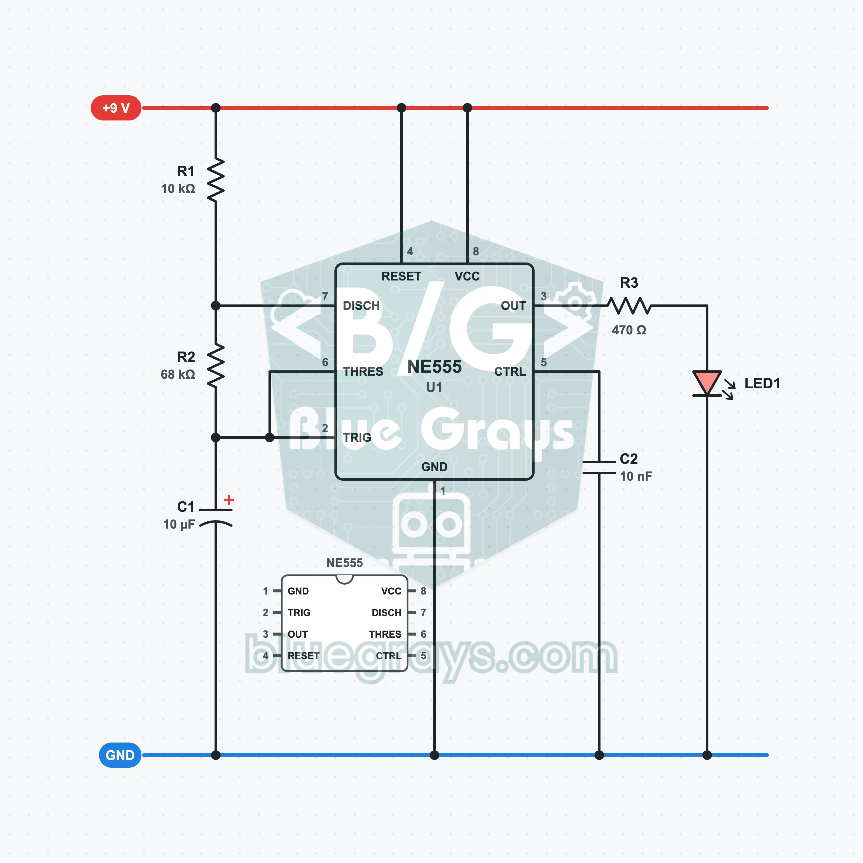
Circuit Diagram
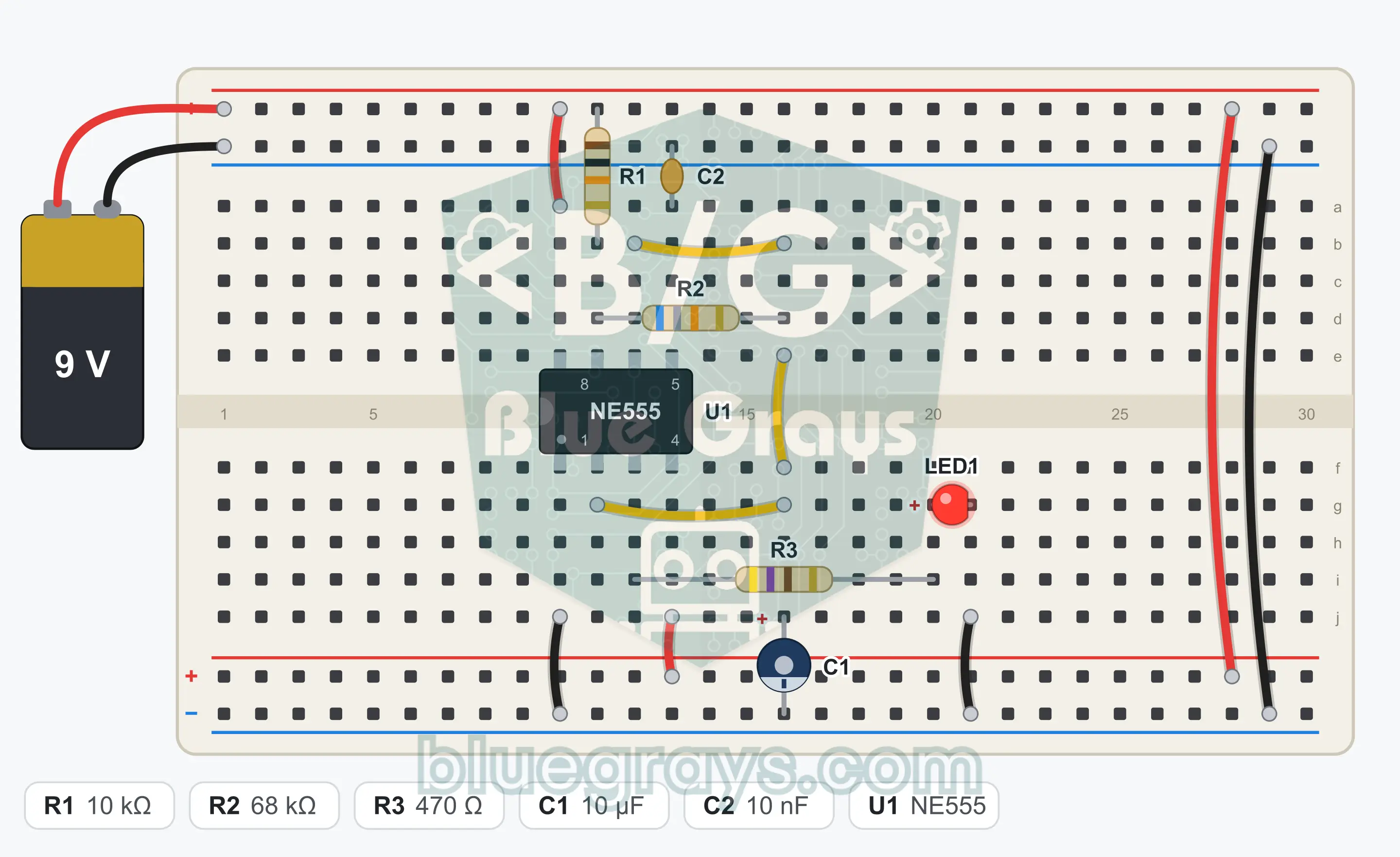
Breadboard Layout
Build Steps
- 1
Place the NE555 (U1) over the center gap of the breadboard with its notch facing left. The pin at the bottom left corner is pin 1; the bottom row runs 1, 2, 3, 4 from left to right, and the top row runs 5, 6, 7, 8 from right to left.
- 2
Connect pin 8 to the + rail of the breadboard with a jumper wire.
- 3
Connect pin 1 to the GND (−) rail with a jumper wire.
- 4
Connect pin 4 (reset) to the + rail with a jumper wire. This way the IC runs all the time.
- 5
Connect pin 2 and pin 6 to each other with a jumper wire.
- 6
Fit R1 (10 kΩ) between the + rail and pin 7.
- 7
Fit R2 (68 kΩ) between pin 7 and pin 6.
- 8
Fit C1 (10 µF): long leg (positive) into the row of pin 6, the short leg on the striped side (negative) into the GND rail.
- 9
Fit C2 (10 nF) between pin 5 and the GND rail. It has no polarity.
- 10
Fit R3 (470 Ω): one end into the row of pin 3, the other end into an empty row.
- 11
Fit LED1: long leg (anode) into the row of R3's free end, short leg (cathode) into the GND rail.
- 12
Plug the red wire of the battery clip into the + rail and the black wire into the GND rail. Compare the connections with the schematic once, then snap the battery onto the clip.
Tip: keep the battery or power supply disconnected while wiring.
Test Steps
- 1
Connect the battery: the LED must start flashing right away.
- 2
Count 10 flashes and time them: it must take about 10 seconds.
- 3
Watch closely: the time the LED stays on is a little longer than the time it stays off.
- 4
Pull the + rail end of the jumper wire on pin 4 out and plug it into the GND rail: the LED goes out and the flashing stops. When you plug the jumper wire back into the + rail, the LED starts flashing again.
How It Works
In astable mode the NE555 generates a square wave by itself and flashes the LED about once a second. The speed is set by R1, R2 and C1.
What is inside the 555?
Inside there are two comparators, a flip-flop and a discharge transistor. The comparators compare the capacitor voltage with 1/3 and 2/3 of the supply. With a 9 V battery these thresholds are 3 V and 6 V.
Charging: the LED lights
While the output (pin 3) is high, the LED is lit. Meanwhile C1 charges from the + rail through R1 and R2. When its voltage reaches 6 V, pin 6 senses this, the flip-flop flips and the output goes low.
Discharging: the LED goes out
When the output goes low, pin 7 is connected to GND internally. C1 now discharges through R2 alone. When its voltage falls to 3 V, pin 2 is triggered, the output goes high again and the cycle starts over.
What sets the speed?
The larger the capacitor and the higher the resistors, the longer charging and discharging take. In this circuit the on time is 0.54 seconds and the off time is 0.47 seconds; together they add up to about 1 second.
What are C2 and R3 for?
C2 protects the control input on pin 5 from noise and keeps the times from drifting. R3 limits the current through the LED to about 11 mA; without it the LED would fail in a short time.
Formulas
On time (output high)
t1 = 0.693 × (R1 + R2) × C1
Example: 0.693 × (10 kΩ + 68 kΩ) × 10 µF = 0.54 s
Off time (output low)
t2 = 0.693 × R2 × C1
Example: 0.693 × 68 kΩ × 10 µF = 0.47 s
Frequency
f = 1.44 / ((R1 + 2 × R2) × C1)
Example: 1.44 / ((10 kΩ + 2 × 68 kΩ) × 10 µF) = 0.99 Hz, that is, about once a second
LED current
I = (Vout − VLED) / R3
Example: (7.3 V − 2 V) / 470 Ω ≈ 11 mA (the output of the 555 is about 1.7 V below the supply)
Common Mistakes
The LED does not light at all.
You may have fitted the LED backwards: the long leg goes to R3, the short leg to GND. Also check that pin 8 is connected to the + rail and pin 1 to the GND rail.
The LED is lit all the time and does not go out.
The jumper wire between pin 2 and pin 6 is missing, or C1 is not connected to this pair. Make sure R2 is between pin 7 and pin 6.
The LED flickers or looks as if it is always lit.
C1 and C2 may have been swapped. The 10 µF electrolytic capacitor must be on pin 6 and the 10 nF ceramic capacitor on pin 5.
The IC heats up.
Disconnect the battery at once. The 555 may be fitted backwards, or R1 may have been left out and pin 7 connected directly to the + rail.
FAQ
How do I change the flashing speed of the LED?
The speed is set by C1 and R2. If you make C1 larger or increase R2, the LED slows down; if you make them smaller, it speeds up. For example, if you fit 22 µF in place of C1 the LED flashes about once every 2.2 seconds, and with 4.7 µF about once every half second.
Can I use a different supply instead of the 9 V battery?
Yes. The NE555 works between 4.5 V and 16 V. With 5 V or 6 V the same circuit flashes at the same speed, because the thresholds move together as 1/3 and 2/3 of the supply voltage. The LED just lights a little dimmer.
Is the 10 nF capacitor on pin 5 really necessary?
The circuit works without it too. Pin 5 is the control input that leads to the internal 2/3 threshold. If it is left floating, noise in the surroundings can shift the threshold and the times drift a little. The 10 nF drains this noise to GND; I recommend always fitting it as a habit.
Why doesn't the LED flash exactly half on, half off?
The capacitor charges through R1 and R2 but discharges through R2 alone. Because the charging path has more resistance, the LED's on time (0.54 s) is a little longer than its off time (0.47 s). The smaller R1 is compared with R2, the closer the two times get.