
555 Flip-Flop: Two-Button Memory Circuit
Press one button and the LED lights; take your finger off and it stays lit. Press the other button and it goes out. The bistable mode of the NE555 uses the flip-flop inside it directly: no counting time with a capacitor, only SET and RESET. This circuit is the easiest form of 1-bit memory to build and is ideal for seeing flip-flop logic for the first time.
Video
Circuit Diagram
Breadboard Layout
Build Steps
- 1
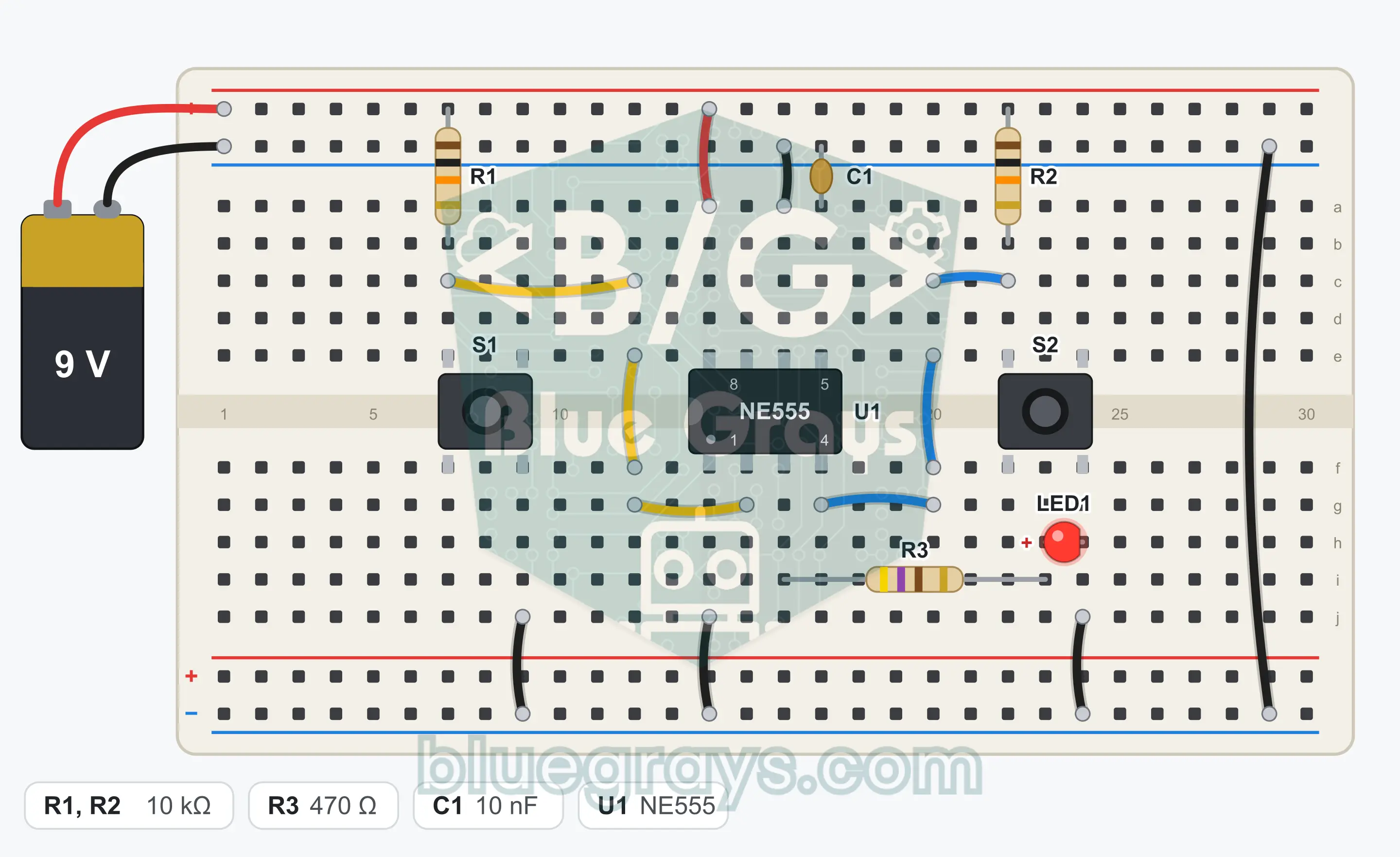
Place the NE555 (U1) over the center gap of the breadboard with its notch facing left. The bottom left corner is pin 1; the bottom row runs 1, 2, 3, 4, and the top row runs 5, 6, 7, 8 from right to left.
- 2
Connect pin 8 to the + rail with a jumper wire.
- 3
Connect pin 1 to the GND (−) rail with a jumper wire.
- 4
Connect pin 6 to the GND rail with a jumper wire. The threshold input is not used in this circuit.
- 5
Fit R1 (10 kΩ) between the + rail and pin 2.
- 6
Fit R2 (10 kΩ) between the + rail and pin 4.
- 7
Place the S1 button over the center gap and connect the leg at one corner to pin 2 with a jumper wire.
- 8
Connect the leg at the diagonally opposite corner of S1 to the GND rail with a jumper wire.
- 9
Place the S2 button over the center gap and connect the leg at one corner to pin 4 with a jumper wire.
- 10
Connect the leg at the diagonally opposite corner of S2 to the GND rail with a jumper wire.
- 11
Fit C1 (10 nF) between pin 5 and the GND rail.
- 12
Fit R3 (470 Ω): one end into the row of pin 3, the other end into an empty row.
- 13
Fit LED1: long leg (anode) into the row of R3's free end, short leg (cathode) into the GND rail.
- 14
Pin 7 stays unconnected. Plug the red wire of the battery clip into the + rail and the black wire into the GND rail, compare with the schematic and snap the battery onto the clip.
Tip: keep the battery or power supply disconnected while wiring.
Test Steps
- 1
Connect the battery. The LED may start lit or unlit; both are normal.
- 2
Press S1 once briefly and release it: the LED must light and stay lit.
- 3
Press S2 once briefly and release it: the LED must go out and stay off.
- 4
Press S1 several times in a row: if the LED is already lit, nothing must change.
- 5
Press both buttons together: the LED goes out, because reset is dominant.
How It Works
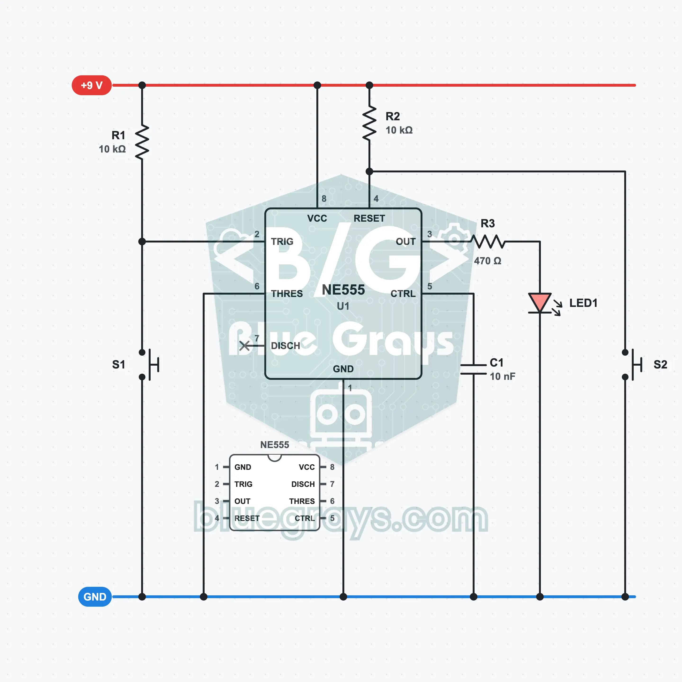
In bistable mode the NE555 works like a 1-bit memory: S1 lights the LED, S2 turns it off, and the state is kept after you release the button.
The flip-flop inside the 555
Inside the NE555 there is an SR flip-flop that controls the output. In the timer modes this flip-flop is set and reset by the capacitor voltage. In bistable mode you take the capacitor out of the picture and control the flip-flop yourself with the buttons.
S1: set (SET)
R1 holds pin 2 at 9 V while it is idle. When you press S1, pin 2 drops to GND. When the voltage falls below 1/3 of the supply (3 V), the flip-flop is set, the output goes high and the LED lights. When you release the button, the state does not change.
S2: reset (RESET)
R2 holds pin 4 at 9 V while it is idle. When you press S2, pin 4 drops to GND and below about 0.7 V the flip-flop is reset. The output goes low, the LED goes out and it stays that way until a new SET arrives.
Why is there no capacitor?
Because pin 6 is at GND, the threshold comparator never comes into play; the circuit does not count time. That is also why pin 7 is left unconnected. The only capacitor is C1, the 10 nF that protects pin 5 from noise.
Truth Table
| S1 (SET) | S2 (RESET) | Output (LED) |
|---|---|---|
| Not pressed | Not pressed | Previous state is kept |
| Pressed | Not pressed | 1 (lights) |
| Not pressed | Pressed | 0 (goes out) |
| Pressed | Pressed | 0 (reset dominant) |
Pressing a button pulls the related pin to GND; both inputs are active-low.
Formulas
SET threshold
Vtrig = Vcc / 3
Example: 9 V / 3 = 3 V; the output goes high when pin 2 falls below this value
Current through the resistor while the button is pressed
I = Vcc / R1
Example: 9 V / 10 kΩ = 0.9 mA
LED current
I = (Vout − VLED) / R3
Example: (7.3 V − 2 V) / 470 Ω ≈ 11 mA
Common Mistakes
The LED does not light when I press S1.
If R2 is missing, the 555 stays in reset all the time. Check that pin 4 is connected to the + rail through 10 kΩ, and check the direction of the LED.
The LED goes out when I release the button.
Pin 6 is not connected to GND. Connect it directly to the GND rail with a short jumper wire.
S2 does not turn the LED off.
Take the button's connections from diagonally opposite corners; the two legs on the same side are already connected inside.
The LED changes by itself when touched.
R1 or R2 is not seated properly. A floating input picks up noise from the surroundings; plug both resistors firmly into the + rail.
FAQ
Why does this circuit count as a flip-flop?
A flip-flop is a circuit that has two stable states and remembers the last command it was given. Here the output is either high or low and does not change unless you press a button. S1 does the set job (SET) and S2 the reset job (RESET); in other words, this is an SR flip-flop.
What happens if I press both buttons at once?
Reset wins. On the NE555, while pin 4 is low the output stays low whatever the trigger input says, and the LED goes out. If you release S2 first while S1 is still pressed, the LED lights; if you release S1 first, the LED stays off.
Why is pin 6 connected to GND?
Pin 6 is the threshold input; if its voltage goes above 2/3 of the supply, it sends the output low. Because we are not counting time in bistable mode, we want this input never to be triggered. Connecting it to GND takes the threshold comparator out of action.
When I connect the battery, does the LED start lit or unlit?
There is no guarantee; at power-on the internal flip-flop falls into one of its two states. Most of the time it starts off, but it can start lit too. If you want it to start off for certain, add a 100 nF capacitor between pin 4 and GND: it produces a short reset at power-on.