
EL-28BeginnerPremium555 timer circuits
Adjustable-Speed Flasher: 555 Circuit with a Potentiometer
Replace the fixed resistor in the 555 Flasher circuit with a potentiometer to adjust the LED's flashing speed by hand. At one end, it flashes about 1.3 times a second; at the other, about 10 times. Learn how to wire the pot as an adjustable resistor, what the frequency formula gives at both ends and how the fixed 1 kΩ resistor in series with the pot protects the 555.
0.0(0)
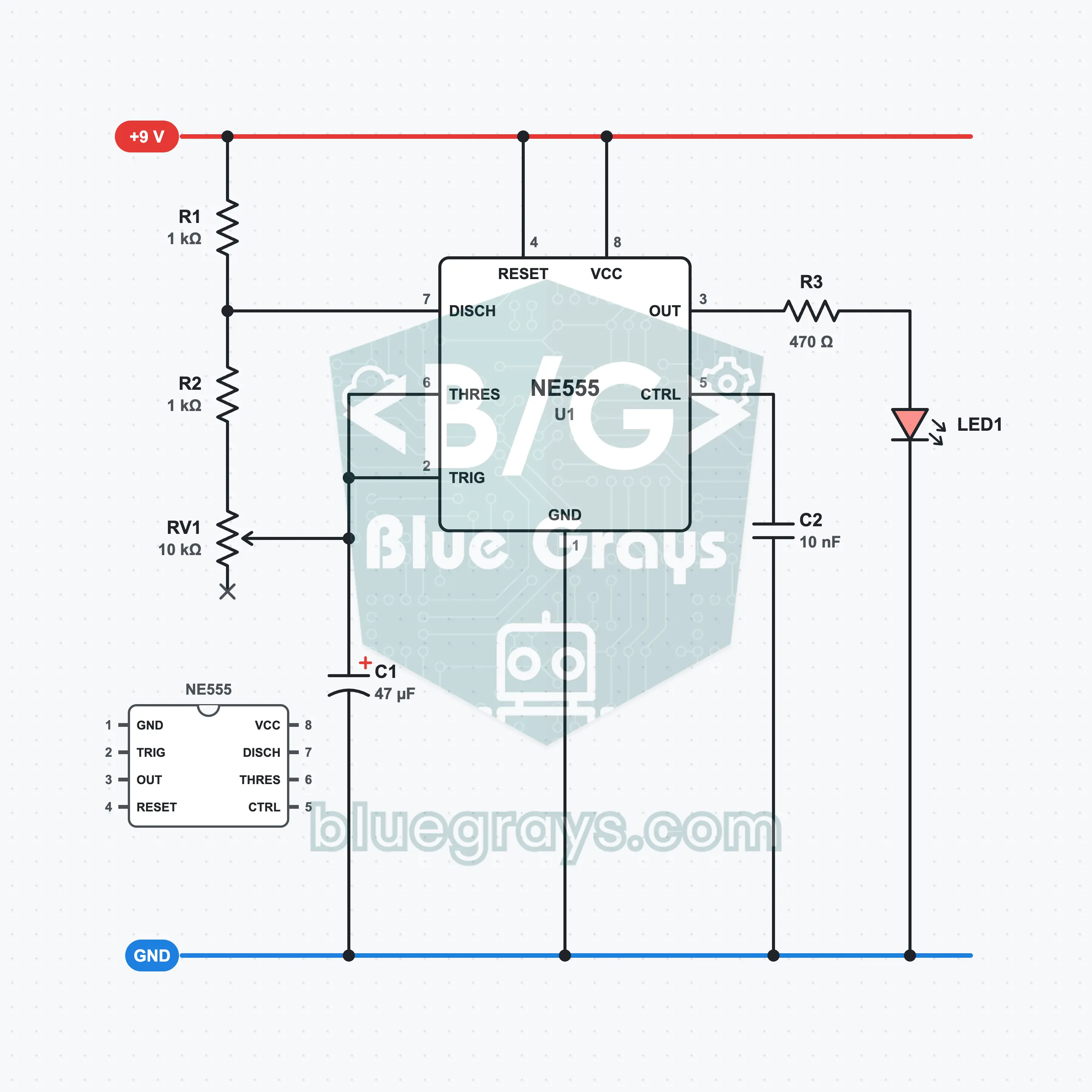
It is built with a 9 V battery, one NE555, a 10 kΩ potentiometer, two 1 kΩ resistors and one 470 Ω resistor, 47 µF and 10 nF capacitors and one LED. The pot changes the resistance between pin 7 and pin 6 from 1 kΩ to 11 kΩ; the frequency varies from about 1.3 Hz to 10 Hz. At the slowest end you can count the flashes; at the fastest end you see the LED flicker. What you learn: wiring the pot as an adjustable resistor, astable frequency calculation, the ratio of on and off times and the protective resistor.
Premium Content
This circuit's build steps, how-it-works guide and FAQ are open to Premium members.
- Build Steps
- How It Works
- Frequently Asked Questions