
555 Timer: Press the Button, Light for 5 Seconds
Press the button once and the LED lights for about 5 seconds, then goes out by itself. This circuit is the NE555's monostable mode, that is, its one-shot mode: the basis of staircase light timers, delayed lamps and timers. The time is set by just one resistor and one capacitor. You try out the trigger input, the threshold voltage and the formula T = 1.1 × R × C in a circuit you built yourself.
Video
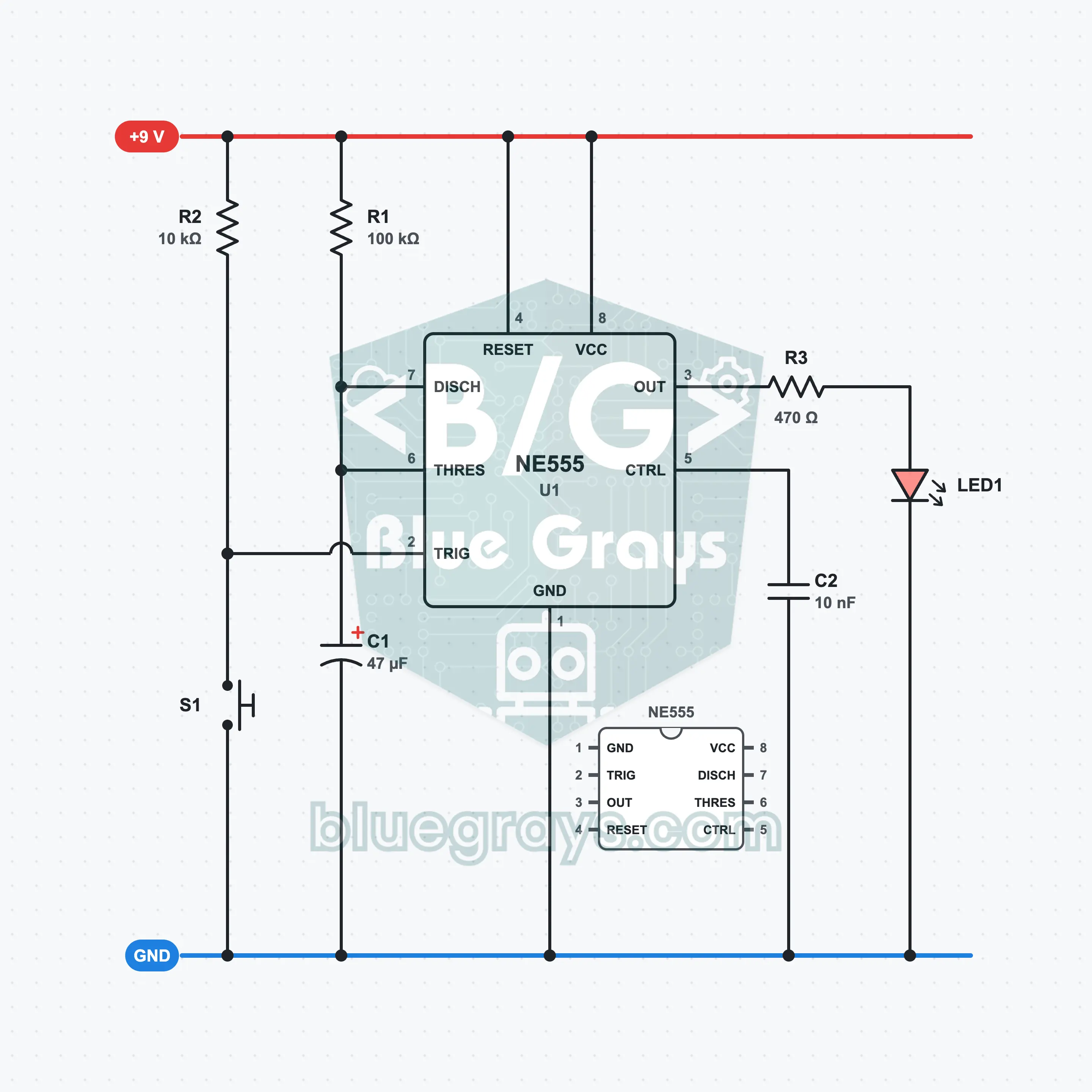
Circuit Diagram
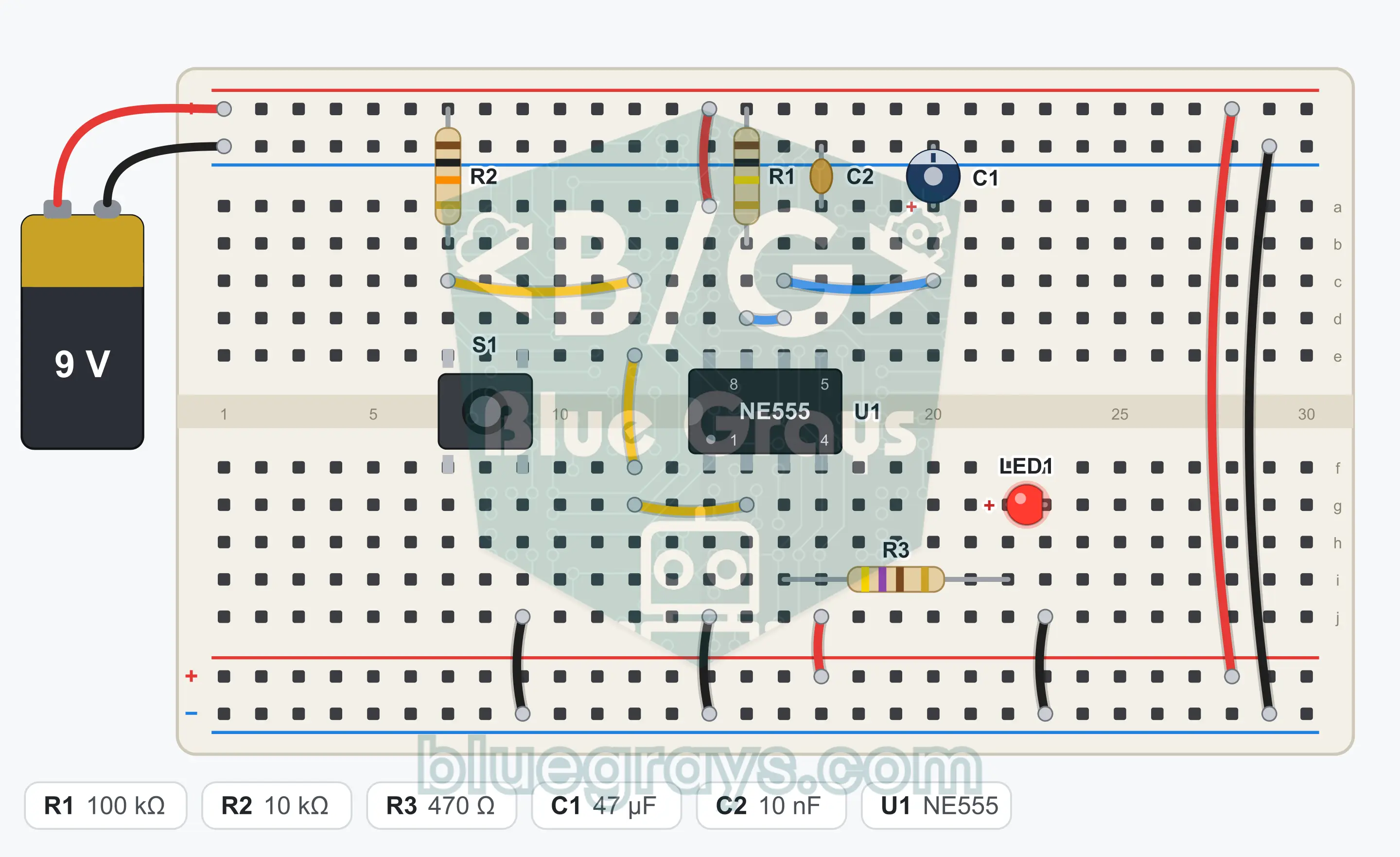
Breadboard Layout
Build Steps
- 1
Place the NE555 (U1) over the center gap of the breadboard with its notch facing left. The bottom left corner is pin 1; the bottom row runs 1, 2, 3, 4, and the top row runs 5, 6, 7, 8 from right to left.
- 2
Connect pin 8 to the + rail with a jumper wire.
- 3
Connect pin 1 to the GND (−) rail with a jumper wire.
- 4
Connect pin 4 (reset) to the + rail with a jumper wire.
- 5
Connect pin 6 and pin 7 to each other with a short jumper wire.
- 6
Fit R1 (100 kΩ) between the + rail and pin 7.
- 7
Fit C1 (47 µF): long leg (positive) into the row of pin 6, the short leg on the striped side (negative) into the GND rail.
- 8
Fit R2 (10 kΩ) between the + rail and pin 2. This resistor holds the trigger input high while it is idle.
- 9
Place the push button (S1) next to the IC, over the center gap.
- 10
Connect the leg at one corner of the button to pin 2 with a jumper wire.
- 11
Connect the leg at the diagonally opposite corner of the button to the GND rail with a jumper wire.
- 12
Fit C2 (10 nF) between pin 5 and the GND rail.
- 13
Fit R3 (470 Ω): one end into the row of pin 3, the other end into an empty row.
- 14
Fit LED1: long leg (anode) into the row of R3's free end, short leg (cathode) into the GND rail.
- 15
Plug the red wire of the battery clip into the + rail and the black wire into the GND rail. Compare with the schematic, then snap the battery onto the clip.
Tip: keep the battery or power supply disconnected while wiring.
Test Steps
- 1
Connect the battery. The LED must wait unlit. If it lights once at first and goes out after 5 seconds, there is no problem; some 555s trigger themselves at power-on.
- 2
Press the button once briefly and start counting: the LED must light and go out by itself after about 5 seconds.
- 3
Press the button a few more times while the LED is lit: the time must not get longer, and the LED must go out 5 seconds after the first press.
- 4
Hold the button down for 8 seconds: the LED stays lit until you let go, and goes out when you release it.
How It Works
In monostable mode the NE555 produces a single pulse at every press of the button: the LED lights for about 5 seconds and goes out by itself. The time is set by R1 and C1.
Standby state
While the button is not pressed, R2 holds pin 2 at 9 V. The output of the 555 is low and the LED is off. Because pin 7 is connected to GND internally, C1 stays discharged.
Triggering
When you press the button, pin 2 drops to GND. The moment the voltage falls below 1/3 of the supply (3 V), the internal flip-flop is set: the output goes high, the LED lights and pin 7 releases the capacitor.
Counting: the capacitor charges
C1 charges slowly through R1. The larger the resistor, the smaller the current and the longer the charging takes. Meanwhile the 555 watches the capacitor voltage on pin 6.
The time is up
When the C1 voltage reaches 2/3 of the supply (6 V), the flip-flop is reset. The output goes low, the LED goes out and pin 7 discharges the capacitor in an instant. The circuit starts waiting for a new press.
Formulas
Time
T = 1.1 × R1 × C1
Example: 1.1 × 100 kΩ × 47 µF = 5.17 s
Trigger threshold
Vtrig = Vcc / 3
Example: 9 V / 3 = 3 V; the time starts when pin 2 falls below this value
End threshold
Vth = 2 × Vcc / 3
Example: 2 × 9 V / 3 = 6 V; the time ends when C1 reaches this value
LED current
I = (Vout − VLED) / R3
Example: (7.3 V − 2 V) / 470 Ω ≈ 11 mA
Common Mistakes
Nothing happens when I press the button.
Take the button's connections from diagonally opposite corners. Check the direction of the LED and the supply on pin 8 and pin 1.
The LED never goes out.
If R2 is missing or the button is fitted rotated, pin 2 stays low all the time. Also look at the jumper wire between pin 6 and pin 7 and check that C1 is connected.
The LED only flashes at the moment I press.
C1 and C2 have been swapped. The 47 µF goes to pins 6 and 7, the 10 nF to pin 5.
The time is very different from what I expected.
Check the color code of R1 (brown, black, yellow) and the direction of C1. A deviation of up to 20 percent comes from the capacitor tolerance and is normal.
FAQ
How do I make the time longer or shorter?
The time is found with T = 1.1 × R1 × C1. If you make R1 or C1 larger, the time gets longer. If you fit 220 kΩ in place of R1 you get about 11 seconds, and with 47 kΩ about 2.4 seconds. For minutes you need large values such as 1 MΩ and 100 µF.
If I press the button again while the LED is lit, does the time get longer?
No. While the time is running the NE555 ignores new triggers; the count continues from the first press. When you press after the time is up, a new 5 seconds starts. The only exception is when the button is still pressed at the moment the time runs out.
What happens if I hold the button down?
The output stays high as long as pin 2 stays low. So if you hold the button for longer than 5 seconds, the LED stays lit until you let go and goes out the moment you release it. For the timer to work properly, a short press and release is enough.
Why doesn't the time come out at exactly 5.17 seconds?
The calculation is for ideal parts. The real value of an electrolytic capacitor can differ from its printed value by about 20 percent, and it also has a small leakage current. That is why results between 4 and 6.5 seconds are normal. For precise timing a good-quality capacitor is chosen.