
Write Arduino Code with AI: Better Prompts, Testing and Fixes
Write Arduino code with AI tools like ChatGPT: a prompt template, checks before uploading, made-up functions, wrong pins, delay() lockups and mains safety.
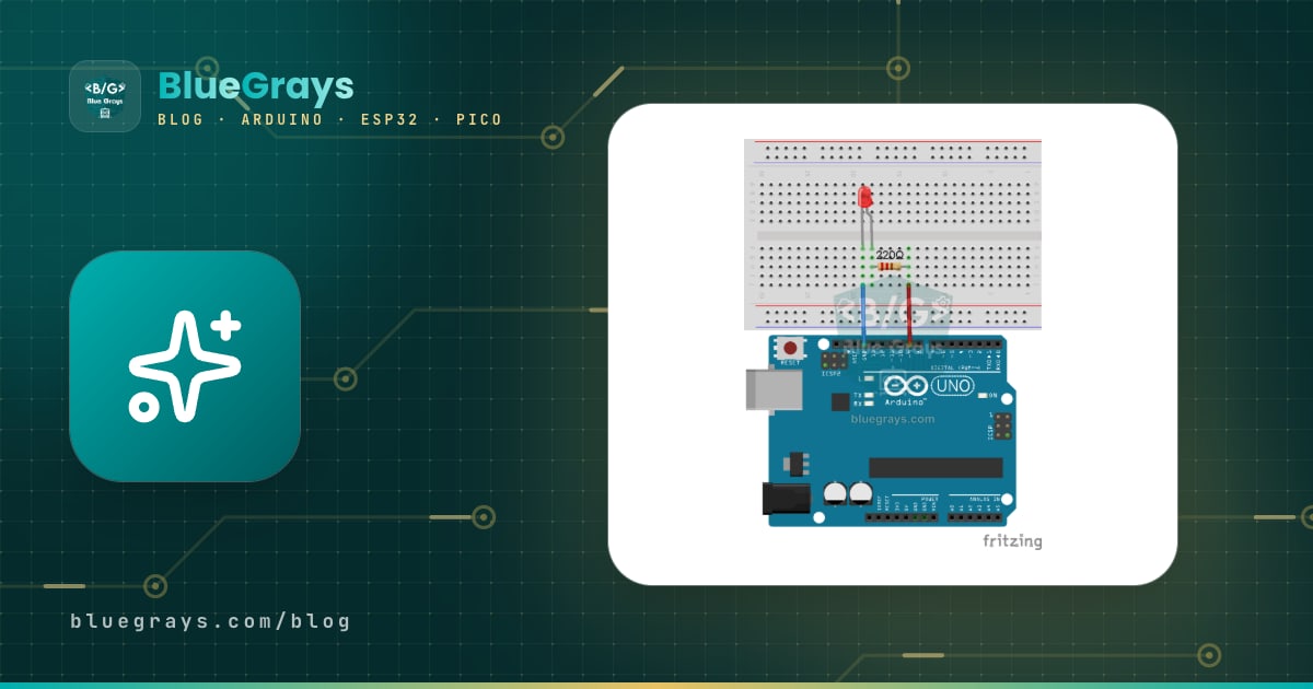
Writing Arduino code with AI means describing your project to a chat assistant such as ChatGPT, Gemini, Claude or Copilot and asking it for working code for an Arduino, ESP32 or Raspberry Pi Pico. Used well, it turns hours of work into minutes: instead of a blank page you get a draft that's ready to compile. But the AI can't see your circuit, doesn't know which board is on your desk and can state something wrong with complete confidence. It may invent a library function that doesn't exist, pick the wrong pin or write delay() loops that freeze everything. That's why the real skill isn't asking for code, it's asking well and verifying what comes back.
In this guide you'll see how an AI assistant produces Arduino code and why it gets things wrong, how to write a good prompt that covers the board, pins, libraries and expected behaviour, and which steps to follow to verify the code before you upload it. We'll go through the three most common mistakes with real compiler messages and corrected code. Then we'll cover the right way to paste a compilation error and get it fixed, why you shouldn't trust AI when working with mains voltage, and how to use these tools without giving up on learning.
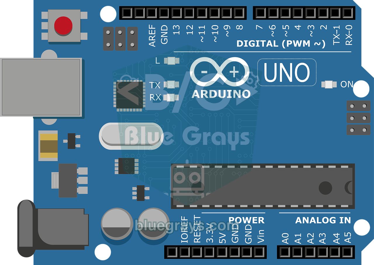
How does AI write Arduino code, and why does it get it wrong?
Large language models (LLMs) like ChatGPT don't write code by running it like a compiler; they write it by predicting the most likely continuation based on the millions of examples they saw during training. For topics with plenty of examples online (blinking an LED, reading a DHT11, turning a servo) this works very well. But the model's knowledge is frozen at a certain date, so it may not know about functions that changed in newer library versions. It can mix up the functions of two different libraries that share the same name. Most importantly, instead of saying "I don't know", it may make up an answer that sounds plausible; this is called hallucination. Because the model can't see your circuit, it works out pin numbers, voltage levels and module versions either from what you wrote or from its own guesses.
| Task | How good is AI at it? | Why? |
|---|---|---|
| Simple example code (LED, button, sensor reading) | Very good | There are thousands of similar examples online |
| Explaining existing code line by line | Very good | Reading and explaining code doesn't require guessing |
| Finding the cause of a compilation error | Good | Error messages follow patterns that models recognise |
| Code for the latest library version | Weak | Its knowledge is frozen at a certain date; it may not know new functions |
| Choosing pins that match your circuit | Weak | It can't see your board or wiring, so it assumes |
| Timing and doing several things at once | Fair | Most examples use delay(), so it produces blocking code |
| Mains voltage, batteries and high-current circuits | Unreliable | Mistakes cost burns, fires or electric shock; the model can't take responsibility |
How do you write a good prompt?
The code an AI gives you can't be better than the information you give it. With a one-line request like "write Arduino code to measure temperature", the model picks the board, sensor, pin and library itself. If its choices don't match what you have, the code either won't compile or will compile and not work. Write a good prompt the way you'd explain the project over the phone to a friend hearing about it for the first time: name the board, components, connections, libraries, expected behaviour and constraints one by one. The table below sums up what an Arduino prompt should contain:
| What belongs in the prompt? | Why it matters | Example |
|---|---|---|
| Exact board name | Pins, voltage and commands differ between Uno, ESP32 and Pico | Arduino Uno R3 (ATmega328P) |
| IDE and core version | On the ESP32, functions changed between core 2.x and 3.x | Arduino IDE 2.3, esp32 core 3.x |
| Component part numbers | DHT11 and DHT22, or SG90 and MG996R, aren't the same | DHT22, 16x2 I2C LCD (PCF8574, address 0x27) |
| Pin connections | The model follows your wiring instead of inventing pins | DHT22 DATA → D2, button between D3 and GND |
| Library name and author | Different libraries with the same name use different functions | Adafruit DHT sensor library, Frank de Brabander LiquidCrystal I2C |
| Expected behaviour in numbers | "Beep when it gets hot" is vague, "above 30 °C" is measurable | Measure every 2 seconds, beep the buzzer 3 times above 30 °C |
| Constraints | Stops the model's bad habits from the start | Don't use delay(), use millis() |
| Output format | You get the code and the setup information together | A single .ino file, comments in English, a list of required libraries |
For example, this prompt gives far better results than a one-line request: "I'm using an Arduino Uno R3 and Arduino IDE 2.3. The DHT22's DATA pin is on D2, an active buzzer is on D8, and a 16x2 I2C LCD (PCF8574, address 0x27) has SDA on A4 and SCL on A5. The Adafruit DHT sensor library and Frank de Brabander's LiquidCrystal I2C library are installed. Every 2 seconds, show temperature and humidity on the LCD, and if the temperature goes above 30 °C, beep the buzzer in short bursts. Use millis() instead of delay() and comment the lines. At the top, list the libraries I need to install, and at the end, list the assumptions you made." With this prompt there's almost nothing left for the model to guess.
Steps to verify AI-generated code
However neat the code looks, run it through a checklist before uploading it to your board. Most of these steps take a few minutes and are far cheaper than a module burned out by a wrongly connected pin:
- Compile it first: Press Verify (the tick button) without the board connected. If you get an error, have it fixed with the method below; for what the messages mean, see Arduino compilation errors.
- Check the libraries one by one: Search for every #include line in the Library Manager and install the library whose name, author and examples match the code. If you're not sure how, the how to add an Arduino library guide walks you through it.
- Compare the pins: Compare every pin number in the code with your own wiring and the board's pin map. Use the Pinout tool for PWM pins and pins you should avoid.
- Calculate the electrical values: Check the suggested resistor value with the LED resistor calculator. If a sensor with a 5 V output goes to a 3.3 V ESP32 or Pico, put a voltage divider in between.
- Try it in a simulator: Run the code in Wokwi or Tinkercad before connecting real hardware; you'll catch logic errors without risking any parts.
- Test piece by piece: Don't upload the whole project at once. First try a small sketch that only reads the sensor and prints to the Serial Monitor, then add the display, and the buzzer or relay last.
- Watch the Serial Monitor: Add Serial.println() at key points to see whether variables take the values you expect, and make sure the baud rate matches Serial.begin() in the code. More in Arduino Serial Monitor.
- Have the code explained: For every line you don't understand, ask "what does this line do, and what happens if I delete it?" Never upload code you can't explain.
Common mistake 1: library functions that don't exist
AI's sneakiest mistake is writing functions that don't actually exist but have very plausible names. For example, the standard Servo library has attach(), write(), writeMicroseconds(), read() and detach(), but no setSpeed() function; the model may invent it when you ask for a slow-moving servo. Sometimes the function really exists, but on another board: Serial.printf() works on the ESP32 but doesn't compile on an Arduino Uno. And sometimes the function belongs to an old version: ledcSetup() and ledcAttachPin() were removed in version 3.x of the ESP32 Arduino core, released in 2024, yet most models still write code with them. Then there are different libraries that use the same header file: in one library called LiquidCrystal_I2C.h the display is started with lcd.init(), in another with the same name it's lcd.begin(). If you see a "Multiple libraries were found" warning in the compiler output, suspect this mix-up.
| What the AI wrote | Compiler message or symptom | Real fix |
|---|---|---|
| Serial.printf("%d", x) on an Uno | 'class HardwareSerial' has no member named 'printf'; did you mean 'print'? | Print piece by piece with Serial.print() or build the text first with snprintf() |
| sprintf(buf, "%.1f", t) on an Uno | Compiles but prints ? instead of the number | On AVR the printf family doesn't support floats; use dtostrf(t, 4, 1, buf) |
| servo.setSpeed(10) | 'class Servo' has no member named 'setSpeed' | Change the angle in small steps in a loop |
| ledcSetup(0, 5000, 8) on ESP32 core 3.x | 'ledcSetup' was not declared in this scope | Use ledcAttach(pin, frequency, resolution) and ledcWrite(pin, value) |
| Only the DHT library installed | fatal error: Adafruit_Sensor.h: No such file or directory | Also install the Adafruit Unified Sensor library |
| lcd.begin() that doesn't match the installed library | no matching function for call to 'LiquidCrystal_I2C::begin()' | Open the installed library's own example and use its start-up command (such as lcd.init()) |
| analogReadResolution(12) on an Uno | 'analogReadResolution' was not declared in this scope | The Uno's ADC is 10-bit; delete the line, values range from 0 to 1023 |
The old-function trap on the ESP32: ledcAttach instead of ledcSetup
When you ask for ESP32 code that sets LED brightness or motor speed, the AI will most likely write the trio ledcSetup(channel, frequency, resolution), ledcAttachPin(pin, channel) and ledcWrite(channel, value). That code works on version 2.x of the core. In version 3.x, however, channels are assigned automatically: ledcAttach(pin, frequency, resolution) sets up the pin in one go, and ledcWrite(pin, value) now takes a pin number instead of a channel. You can see which version is installed next to the esp32 package in the Boards Manager. The code below checks the version at compile time, so it works on both cores:
1// ESP32 PWM: çekirdek 2.x ve 3.x ile uyumlu LED soldurma / LED fade for both core 2.x and 3.x
2#include <esp_arduino_version.h>   // ESP_ARDUINO_VERSION_MAJOR için / for ESP_ARDUINO_VERSION_MAJOR
3
4const int LED_PIN = 2;             // çoğu DevKit'te dahili LED / onboard LED on most DevKits
5const uint32_t FREKANS = 5000;     // PWM frekansı, Hz / PWM frequency, Hz
6const uint8_t COZUNURLUK = 8;      // 8 bit: 0-255 / 8-bit: 0-255
7
8#if ESP_ARDUINO_VERSION_MAJOR >= 3
9// Çekirdek 3.x: kanal otomatik seçilir, fonksiyonlar pin alır / Core 3.x: channel is automatic, functions take the pin
10void pwmBaslat() { ledcAttach(LED_PIN, FREKANS, COZUNURLUK); }
11void pwmYaz(uint32_t deger) { ledcWrite(LED_PIN, deger); }
12#else
13// Çekirdek 2.x: önce kanal kurulur, sonra pine bağlanır / Core 2.x: set up a channel, then attach the pin
14const uint8_t KANAL = 0;
15void pwmBaslat() { ledcSetup(KANAL, FREKANS, COZUNURLUK); ledcAttachPin(LED_PIN, KANAL); }
16void pwmYaz(uint32_t deger) { ledcWrite(KANAL, deger); }
17#endif
18
19void setup() {
20  Serial.begin(115200);
21  Serial.print("ESP32 Arduino cekirdegi / core: ");
22  Serial.println(ESP_ARDUINO_VERSION_MAJOR);
23  pwmBaslat();
24}
25
26void loop() {
27  // Tek iş yaptığı için burada delay() sorun değil / delay() is fine here: only one task
28  for (int d = 0; d <= 255; d++) { pwmYaz(d); delay(4); }   // yavaşça yan / fade in
29  for (int d = 255; d >= 0; d--) { pwmYaz(d); delay(4); }   // yavaşça sön / fade out
30}
The lesson here isn't only about the ESP32: if you include the core and library versions in your prompt, the model has a chance to pick the right functions. If it still uses old functions after you've given the version, open one of the library's official examples from the File > Examples menu and paste it into the prompt with "rewrite it using the functions in this example". Official examples always match the installed version. If you're curious how PWM works, have a look at What is PWM?
Common mistake 2: choosing the wrong pin
Even if the code compiles and uploads, a wrong pin means a circuit that silently does nothing or a module that burns out. The compiler can't catch it, because to the compiler a pin number is just a number. These are the pin mistakes AI makes most often, board by board:
| Board | Common AI mistake | What happens? | The right way |
|---|---|---|---|
| Arduino Uno | A non-PWM pin for analogWrite() (e.g. D7) | The LED doesn't dim: below 128 it's off, from 128 up it's fully on | PWM pins: 3, 5, 6, 9, 10, 11 |
| Arduino Uno | Connecting a module to D0 or D1 | Uploads can fail and the Serial Monitor may show garbage | D0 and D1 are the USB serial line; start from D2 |
| Arduino Nano | Using A6 and A7 as digital pins | digitalRead() and digitalWrite() don't work | A6 and A7 are analog inputs only |
| ESP32 | Using GPIO 6–11 | The board crashes or keeps rebooting | These pins are tied to the flash memory; pick safe pins such as GPIO 4, 5, 16–19, 21–23 |
| ESP32 | Using GPIO 34–39 as outputs | The LED stays off; a button reads erratically without a pull-up | These pins are input-only and have no internal pull-up resistors |
| ESP32 | Reading analog values from ADC2 pins while Wi-Fi is on | analogRead() fails or returns meaningless values | Connect analog sensors to ADC1 pins (GPIO 32–39) |
| Raspberry Pi Pico W | Pin(25) for the onboard LED | The LED stays off | On the Pico W the LED is wired to the wireless chip; use Pin("LED") |
Common mistake 3: delay() lockups
Because most Arduino examples online are written with delay(), AI uses delay() by default too. While delay(1000) runs, the processor does nothing else for a whole second: it doesn't read buttons, check sensors or update the display. In code that does one thing, that's fine. But ask for two things at once, like "blink an LED and beep the buzzer when the button is pressed", and you'll often get code like this:
1// Yapay zekanın sık ürettiği, kilitlenen kod / Blocking code that AI often produces
2const int BUTON_PIN = 2;    // buton: D2 ile GND arası / button between D2 and GND
3const int LED_PIN = 13;     // dahili LED / onboard LED
4const int BUZZER_PIN = 8;   // aktif buzzer / active buzzer
5
6void setup() {
7  pinMode(BUTON_PIN, INPUT_PULLUP);
8  pinMode(LED_PIN, OUTPUT);
9  pinMode(BUZZER_PIN, OUTPUT);
10}
11
12void loop() {
13  digitalWrite(LED_PIN, HIGH);
14  delay(1000);                          // 1 sn boyunca buton okunmaz / button is not read for 1 s
15  digitalWrite(LED_PIN, LOW);
16  delay(1000);                          // 1 sn daha kör bekleme / another blind second
17
18  if (digitalRead(BUTON_PIN) == LOW) {  // yalnızca tam bu anda basılıysa / only if pressed right now
19    digitalWrite(BUZZER_PIN, HIGH);
20    delay(200);
21    digitalWrite(BUZZER_PIN, LOW);
22  }
23}
This code compiles without errors, but most of the time nothing happens when you press the button. About 2 seconds of each loop() pass are spent inside the two delay() calls, and the button is only read for a few microseconds between them. A short press almost always misses that moment; to be sure the buzzer sounds, you have to hold the button for more than 2 seconds. The fix isn't waiting, it's checking the clock: millis() returns the milliseconds since the board started, each task checks whether its time has come, and loop() runs thousands of times per second:
1// millis() ile kilitlenmeyen sürüm / Non-blocking version with millis()
2const int BUTON_PIN = 2;    // buton: D2 ile GND arası / button between D2 and GND
3const int LED_PIN = 13;     // dahili LED / onboard LED
4const int BUZZER_PIN = 8;   // aktif buzzer / active buzzer
5
6const unsigned long LED_ARALIK = 1000;  // LED değişim aralığı, ms / LED toggle interval, ms
7const unsigned long BIP_SURE = 200;     // bip süresi, ms / beep length, ms
8const unsigned long SICRAMA = 30;       // debounce süresi, ms / debounce time, ms
9
10unsigned long ledZaman = 0;     // LED'in son değiştiği an / last LED toggle
11unsigned long bipZaman = 0;     // bipin başladığı an / beep start
12unsigned long butonZaman = 0;   // butonun son değiştiği an / last button change
13bool ledDurum = false;
14bool bipCaliyor = false;
15int oncekiButon = HIGH;         // önceki buton seviyesi / previous button level
16
17void setup() {
18  pinMode(BUTON_PIN, INPUT_PULLUP);
19  pinMode(LED_PIN, OUTPUT);
20  pinMode(BUZZER_PIN, OUTPUT);
21}
22
23void loop() {
24  unsigned long simdi = millis();
25
26  // 1) LED: zamanı geldiyse durum değiştir / toggle the LED when its time has come
27  if (simdi - ledZaman >= LED_ARALIK) {
28    ledZaman = simdi;
29    ledDurum = !ledDurum;
30    digitalWrite(LED_PIN, ledDurum ? HIGH : LOW);
31  }
32
33  // 2) Buton: yalnızca basıldığı anı yakala / catch only the moment of the press
34  int buton = digitalRead(BUTON_PIN);
35  if (buton != oncekiButon && simdi - butonZaman >= SICRAMA) {
36    butonZaman = simdi;
37    oncekiButon = buton;
38    if (buton == LOW && !bipCaliyor) {  // HIGH -> LOW: yeni basış / new press
39      bipCaliyor = true;
40      bipZaman = simdi;
41      digitalWrite(BUZZER_PIN, HIGH);
42    }
43  }
44
45  // 3) Buzzer: süre dolunca sustur / silence it when the time is up
46  if (bipCaliyor && simdi - bipZaman >= BIP_SURE) {
47    bipCaliyor = false;
48    digitalWrite(BUZZER_PIN, LOW);
49  }
50}
In this version the LED, button and buzzer work without waiting for each other. A subtraction in the form simdi - ledZaman >= LED_ARALIK gives the right result even when millis() rolls over to zero, roughly every 49.7 days, whereas the millis() > targetTime comparison AI sometimes writes breaks at that rollover. Catching the moment the button goes from HIGH to LOW stops the buzzer from beeping again and again while the button is held, and the 30 ms wait filters out contact bounce (debounce). For the full topic see the Arduino millis() vs delay() guide, and for wiring the button see how to connect a button to Arduino.
Pasting a compilation error and getting it fixed
AI is genuinely good at explaining compilation errors, as long as you give it the whole error and the context. Just writing "the code doesn't work" forces the model to guess. Follow this order:
- When a compilation error appears in Arduino IDE 2, click Copy error messages in the notification at the bottom right, or select and copy the whole text in the output panel. The exit status 1 on the last line is useless on its own; the real cause is in the error: line further up.
- Your prompt should contain, in this order: the board and core version, the complete code, the complete error message, and the names and versions of the installed libraries.
- Before asking for a fix, write "First explain the cause of the error, then show only the lines that need to change". That way the model doesn't rewrite the whole sketch and add new errors, and you learn what changed and why.
- Apply the suggested change and compile again. If a new error appears, paste the topmost error: line again; fix one error at a time.
- If the same error is still there after two or three rounds, break the loop and compile the library's official example. If the example doesn't compile either, the problem isn't your code but your setup: the wrong board selected, a missing library, or two libraries with the same name clashing.
If the error happens during upload rather than compilation (such as "avrdude: stk500_recv(): programmer is not responding" or "Failed to connect to ESP32" on an ESP32), changing the code won't help; you need to check the port, cable, driver and board selection. The Arduino code won't upload guide walks you through those cases. When you ask AI about an upload error, include the whole message and the operating system you're using.
Getting AI to write Raspberry Pi Pico and MicroPython code
The same rules apply when you ask for MicroPython code, but here the AI can also mix up platforms. Code written for Raspberry Pi computers with RPi.GPIO or gpiozero doesn't run on the Pico; on the Pico you use MicroPython's machine module. CircuitPython's board and digitalio modules don't exist in MicroPython either. So put clear information like "Raspberry Pi Pico W, MicroPython, Thonny" in your prompt. The code below runs on both the Pico and the Pico W and uses ticks_ms() for timing instead of waiting:
1# Pico ve Pico W: bekletmeden LED + buton / Pico and Pico W: LED + button without blocking
2from machine import Pin
3import time
4
5led = Pin("LED", Pin.OUT)             # Pico W'da Pin(25) çalışmaz / Pin(25) does not work on Pico W
6buton = Pin(14, Pin.IN, Pin.PULL_UP)  # buton: GP14 ile GND arası / button between GP14 and GND
7
8ARALIK = 500                          # LED değişim aralığı, ms / LED toggle interval, ms
9SICRAMA = 30                          # debounce süresi, ms / debounce time, ms
10son = time.ticks_ms()                 # LED'in son değiştiği an / last LED toggle
11degisim = time.ticks_ms()             # butonun son değiştiği an / last button change
12onceki = 1                            # önceki buton seviyesi / previous button level
13sayac = 0
14
15while True:
16    simdi = time.ticks_ms()
17    if time.ticks_diff(simdi, son) >= ARALIK:      # taşmada da doğru / correct even on overflow
18        son = simdi
19        led.toggle()
20    deger = buton.value()
21    if deger != onceki and time.ticks_diff(simdi, degisim) >= SICRAMA:
22        degisim = simdi
23        onceki = deger
24        if deger == 0:                # basıldığı an / moment of the press
25            sayac += 1
26            print("Basma / press:", sayac)
When you run the code in Thonny, the onboard LED blinks every half second and each button press prints an increasing number in the Shell window. time.ticks_diff() gives the correct difference even when the tick counter wraps around, while the plain time.ticks_ms() - son subtraction AI often writes can give a wrong result in code that runs for a long time. If you're new to the Pico, start with What is the Raspberry Pi Pico?
Mains voltage: don't trust the AI
If your project will run on mains power, test it at low voltage first: use an LED instead of the lamp and a 12 V LED strip instead of the socket. If the system really has to switch mains, some rules aren't negotiable. Unplug the circuit before working on it. The relay must switch the live wire (L), not the neutral. Don't exceed the current and voltage rating printed on the relay module (10 A 250 VAC on most modules), and put the high-voltage side in a closed, insulated enclosure. Cheap relay modules often don't leave enough clearance between the low- and high-voltage sides; where possible, choose a ready-made, certified smart plug or relay box. You'll find relay module wiring in detail in What is a relay module?
Using AI without giving up on learning
If AI writes every sketch for you, you won't know what to do the first day the code doesn't work. If your goal is to learn electronics and programming, use it not as a code machine but as a patient teacher:
- Write it yourself first: Try the code yourself, then ask the AI to review it with "show me the mistakes but don't give me the corrected code".
- Ask for hints, not answers: When you're stuck, say "give me only a hint for the next step".
- Have it explained line by line: After the code is explained, try to explain the same logic in your own words; whatever you can't explain is what you haven't learned yet.
- Type instead of copying: Typing code by hand instead of pasting it teaches you syntax and function names much faster.
- Predict, then test: Before changing a value, predict what will happen (e.g. if LED_ARALIK becomes 200), then upload it and check.
- Quiz yourself: Ask the AI to give you five questions on the topic you've just learned; to brush up on the basics, use Arduino programming basics.
- Follow the rules: For school assignments and science fairs, follow the rules on AI use and say clearly if you used it.
First projects to try with AI
- Temperature display: Show values measured by a DHT11 on an I2C LCD; give the LCD address and the library author in your prompt.
- Parking sensor: Measure distance with an HC-SR04 and beep faster as an obstacle gets closer; ask for millis()-based timing.
- Night light: Turn on an LED when it gets dark using an LDR; read the threshold from the Serial Monitor first and give it as a number in your prompt.
- Wi-Fi LED control: Switch an LED on and off from a page opened on your phone with an ESP32; state the core version in your prompt.
- Your own idea: Pick a project from the Arduino project ideas list and describe it to the AI with the prompt template from this guide.
AI can be the fastest helper at hand while you learn Arduino, as long as you give it the right information, compile what comes back, check the pins, test piece by piece and never upload a line you don't understand. If you're looking for reliable examples to compare AI-written code against, the BlueGrays app has LED, button, DHT11, ESP32 PWM and Pico projects with step-by-step circuit diagrams and tested code.
Frequently asked questions
Can AI write Arduino code?
Yes. Assistants like ChatGPT, Gemini, Claude and Copilot can produce working code for most simple Arduino, ESP32 and Raspberry Pi Pico projects. Before uploading, though, you should compile it and check the pins, libraries and voltage levels yourself; the AI can't see your circuit and can be wrong.
What is the best AI for writing Arduino code?
There's no single right answer; current large models give similar results for simple Arduino code. The difference usually comes from the prompt rather than the model: a prompt that clearly states the board, pin connections, libraries and expected behaviour gets better code whichever assistant you use.
Why doesn't the Arduino code from ChatGPT work?
The most common reasons are functions that don't exist or belong to another board, code written for a different library version, the wrong pins, and delay() calls that block everything. Compile the code first; if there's an error, paste the whole message along with the board and version details. If it compiles but doesn't work, print intermediate values to the Serial Monitor to find where the problem is.
How do I ask AI to fix an Arduino compilation error?
Give the board name, the core and library versions, the complete code and the complete error message from the output panel in one message. If you add "first explain the cause, then show only the lines that change", you get the right fix and learn why the error happened.
Can I trust AI wiring for a mains relay?
No, not on its own. The code is usually fine, but the danger lies in the wiring; the AI can't see your circuit and can't guarantee its instructions are correct. Only wire the mains side with someone knowledgeable, with the plug pulled, using a relay setup that switches the live wire and sits in a closed enclosure; where possible, use a ready-made certified smart plug.
Does using AI hurt learning Arduino?
If you copy code without understanding it, yes; you won't know what to do at the first error. If you write code yourself first and have the AI review it, explain it line by line and give hints instead of answers, it speeds up learning. The rule is simple: never upload a line you can't explain.
Projects to build after reading this
See all projects
LED Blink
The very first hello of electronics: switching a single LED on and off. The Arduino turns the LED on and off at short intervals, so the light blinks quickly. You see in the simplest way how the board

LED Control with a Push Button (Push)
Just like a doorbell: the light stays on as long as you press, and goes off when you let go. The Arduino keeps listening to the button; while it's pressed the LED is on, and the moment you lift your f
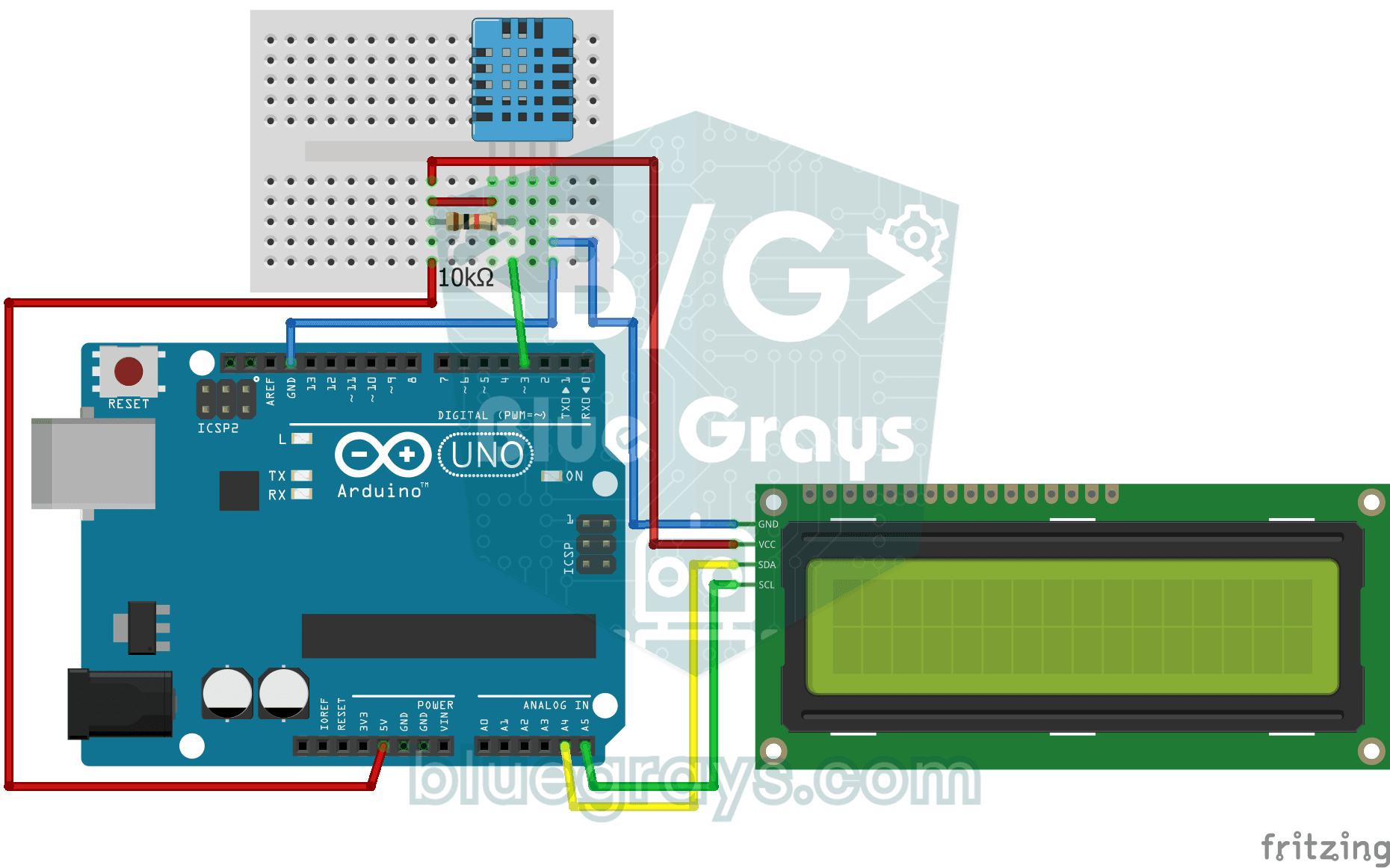
Temperature and Humidity with DHT11
How warm is your room, and is the air humid or dry? The DHT11 sensor measures temperature and humidity, and the Arduino writes the values on a two-line LCD screen, refreshing every couple of seconds.

LED Blink with ESP32
Teaches basic GPIO output usage with ESP32. We achieve a blinking effect by turning an LED on and off from a digital pin. ESP32 version of the classic blink project on Arduino UNO; the basic blink commands in the Arduino environment are the same, but the ESP32's pin layout and 3.3 V GPIO levels differ from those of the Arduino UNO.
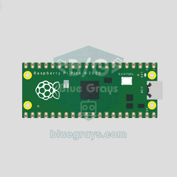
Raspberry Pi Pico Onboard LED Blink (Pico and Pico W)
The opening project of the Raspberry Pi Pico series! We blink the green onboard LED to verify the board works — a classic "Hello World" first experiment. NO external components, just Pico and USB cable. Code is written in MicroPython (the official language backed by Raspberry Pi Foundation). Learn machine.Pin class, Pin.OUT mode, led.on()/off() methods, and time.sleep() in Thonny IDE. Follow every toggle live in the Serial (REPL) output. Also perfect to verify

ESP32 LED Fade with PWM
Smoothly changing the brightness of the LED from 0 to max, from max to 0. We control PWM with analogWrite() as in Arduino - the same syntax as ESP32 Arduino Core 3.0+ works without problems. Pin definition + pinMode + analogWrite is enough.
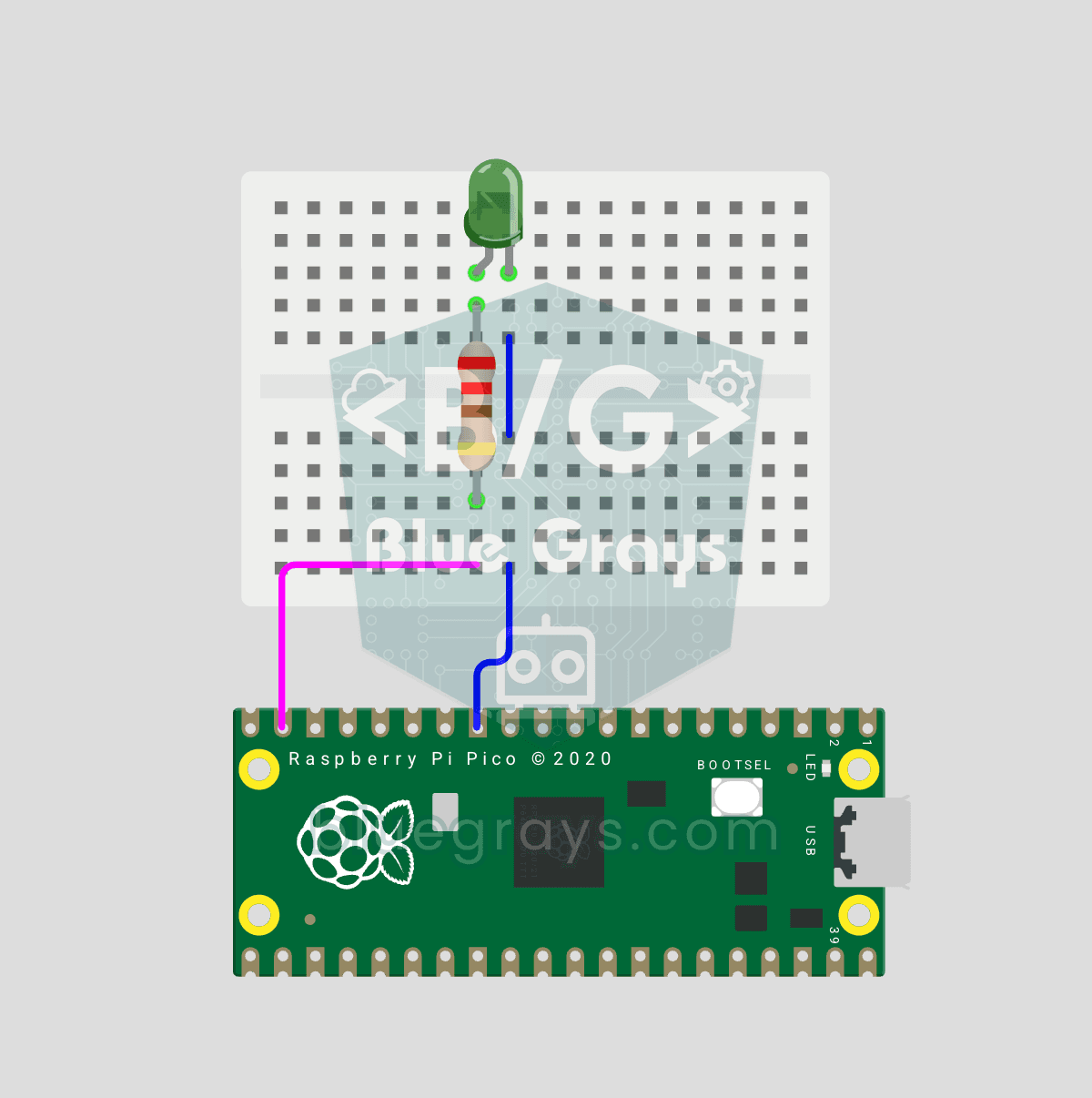
Raspberry Pi Pico PWM LED Fade (Breathing Effect)
The LED no longer just blinks — it breathes! Using the Raspberry Pi Pico's PWM (Pulse Width Modulation), the LED brightness slowly rises and then slowly falls, like a sleeping MacBook's light. Learn the machine.PWM class, duty_u16() (16-bit brightness 0–65535), PWM frequency (freq(1000) — 1000 on/off cycles per second, no visible flicker), range() step loops (up and down) and analog-like output from a digital pin. PWM is a core embedded tool — RGB color mixing, motor
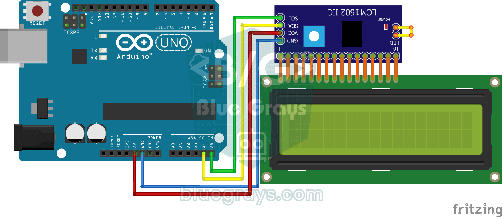
Using LCD Screen with I2C
Give your Arduino its own screen and make it write its first message. The two-line LCD screen hooks up with just a few wires; a greeting appears on the top line, then a second message on the bottom li