
Arduino Uno R4 WiFi vs Minima: R3 Differences and First Project
What's new in the Arduino Uno R4 Minima and WiFi vs the R3? 32-bit RA4M1, 12-bit DAC, the 8 mA pin limit, library compatibility and a LED matrix Wi-Fi project.
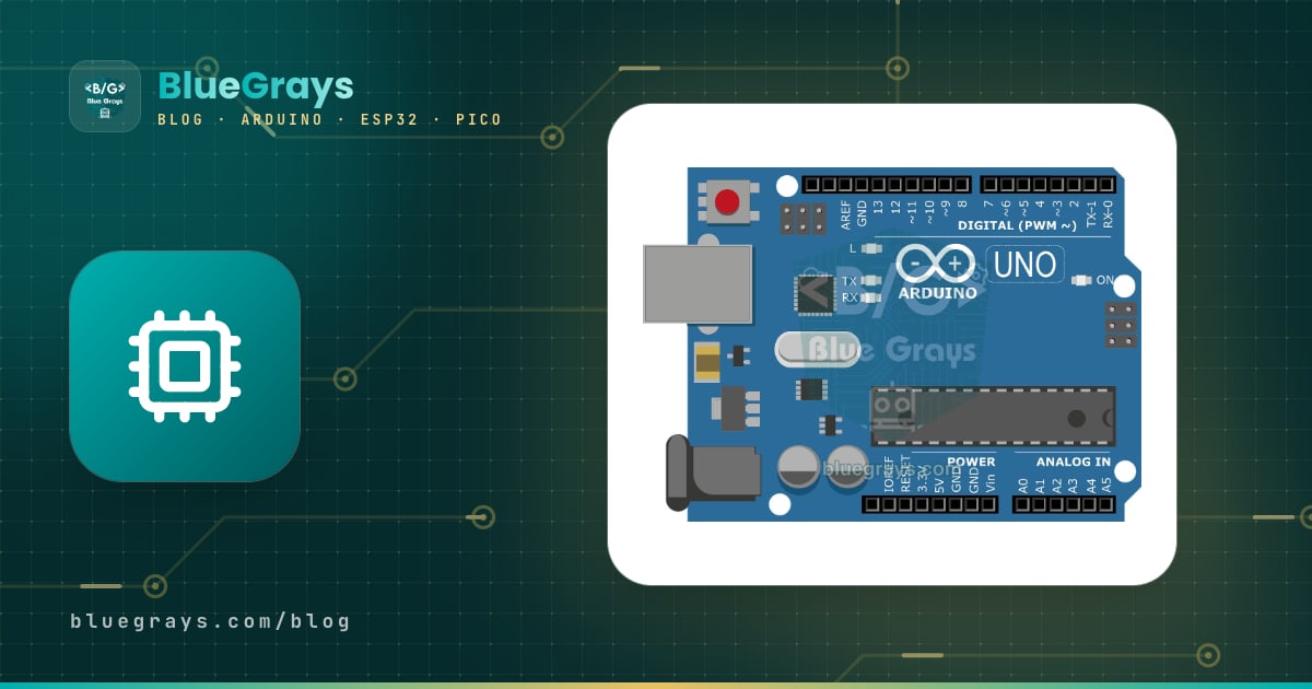
The Arduino Uno R4 is the fourth revision of the Uno, the world's most widely used development board, and the first Uno to use a 32-bit processor instead of an 8-bit AVR. It comes in two models: the simpler, cheaper Uno R4 Minima and the Uno R4 WiFi with Wi-Fi, Bluetooth and a 12x8 LED matrix. Both keep the R3's size, pin layout and 5 V operating voltage, so most shields and circuits plug in as they are. On the other hand, program memory is 8 times larger, the processor is 3 times faster, and it adds a true analog output (DAC), a CAN bus, a built-in clock (RTC) and USB keyboard and mouse support.
In this guide you'll learn exactly where the R4 differs from the R3, how to choose between the Minima and the WiFi, which old sketches and libraries work without trouble and which won't compile, and why you need to respect the 8 mA per-pin limit. At the end we'll build your first project, using the R4 WiFi's LED matrix and Wi-Fi together and controlling it from your phone.
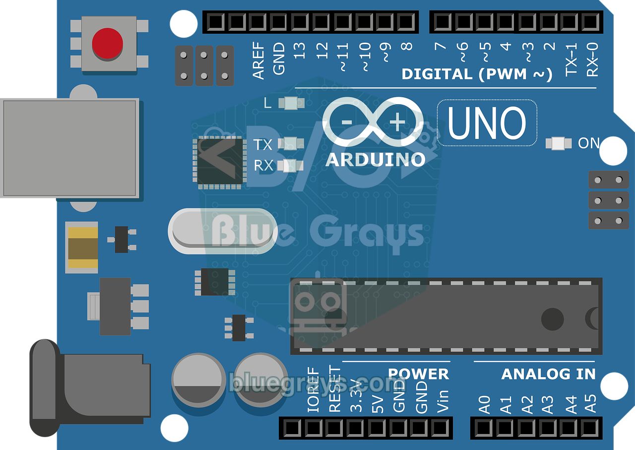
What is the Arduino Uno R4? The Minima and WiFi models
At the heart of both models is Renesas' RA4M1 (R7FA4M1AB3CFM) microcontroller: an Arm Cortex-M4 core running at 48 MHz with a floating-point unit (FPU). Unlike most 32-bit boards, this chip runs at 5 V, which is the main reason Arduino chose the RA4M1 for the R4. The Minima carries only this chip. The WiFi model adds an ESP32-S3-MINI-1 module, which provides Wi-Fi and Bluetooth and also acts as the bridge that talks to your computer over USB. Because the ESP32-S3 runs at 3.3 V, a level shifter sits between the two chips.
| Feature | Uno R4 Minima | Uno R4 WiFi |
|---|---|---|
| Main processor | RA4M1, 32-bit, 48 MHz | RA4M1, 32-bit, 48 MHz |
| Wi-Fi and Bluetooth | None | ESP32-S3: Wi-Fi 4 (2.4 GHz) and Bluetooth 5 LE |
| LED matrix | None | 12x8, 96 red LEDs |
| Qwiic connector | None | Yes (Wire1, 3.3 V only) |
| USB connection | RA4M1's own USB | Bridged through the ESP32-S3 |
| CAN pins | D4 (TX), D5 (RX) | D10 (TX), D13 (RX) |
| Debug header | SWD connector | ESP32-S3 header (3.3 V) |
| Extra pins | None | OFF (power off the board) and VRTC (clock battery) |
| 3.3 V pin | From the RA4M1's internal USB regulator, low current | Separate 3.3 V regulator |
Differences between the Uno R3 and the Uno R4
| Feature | Uno R3 | Uno R4 (Minima and WiFi) |
|---|---|---|
| Processor | ATmega328P, 8-bit, 16 MHz | RA4M1 Cortex-M4, 32-bit, 48 MHz, FPU |
| Flash (program memory) | 32 KB | 256 KB |
| SRAM | 2 KB | 32 KB |
| EEPROM | 1 KB | 8 KB (data flash) |
| Operating voltage | 5 V | 5 V |
| Current per pin | 20 mA recommended, 40 mA absolute maximum | 8 mA |
| Analog input (ADC) | 6 channels, 10-bit | 6 channels, up to 14-bit (10-bit by default) |
| Analog output (DAC) | None | 1 channel, 12-bit (A0) |
| Op-amp | None | Built in (A1, A2, A3) |
| CAN bus | None | Yes (external transceiver required) |
| Real-time clock (RTC) | None | Built in |
| USB | USB-B, ATmega16U2 bridge | USB-C, keyboard and mouse (HID) support |
| VIN input voltage | 7–12 V recommended | 6–24 V |
| Serial port | Serial: USB and D0/D1 shared | Serial: USB, Serial1: D0/D1 |
The most important rows in the table are memory and speed. The R3's 2 KB of SRAM fills up with a few String variables and a display buffer; in projects with an OLED display, long arrays or JSON parsing, the board starts freezing or resetting at random. The R4's 32 KB all but eliminates that problem. Thanks to the FPU, float math (sensor calibration, PID, trigonometry) runs in hardware and is many times faster than on the R3. Power has changed a lot too: the R3's linear regulator gets hot at 12 V, while the R4 uses a switching buck converter, so the board accepts up to 24 V and runs much cooler.
New hardware that comes with the R4
- 12-bit DAC (A0): unlike PWM, it produces a true analog voltage; it's used for audio, sine waves and a simple signal generator. The analogWave library in the board package generates sine, square and sawtooth waves in a single line.
- 14-bit ADC: with analogReadResolution(14) you read values from 0 to 16383; with a 5 V reference one step is about 0.3 mV, versus 4.9 mV on the R3. So that old sketches don't break, the default resolution is still 10-bit.
- Built-in op-amp: on pins A1 (+), A2 (–) and A3 (output); you can amplify small sensor signals without an extra chip. For the basics, see What Is an Op-Amp?
- CAN bus: the robust communication bus used in cars and industry; you use it with a transceiver module such as the SN65HVD230 or TJA1050 and the Arduino_CAN library from the board package.
- RTC: keeps the date and time without an extra module (RTC.h library). On the R4 WiFi, if you connect a battery between 1.6 and 3.6 V to the VRTC pin, the clock keeps running even when the board's power is cut.
- USB HID: the board can show up on your computer as a keyboard or mouse; this used to require a Leonardo (USB keyboard with the Arduino Leonardo).
- Capacitive touch: some pins can work as touch buttons without an extra module, using the Arduino_CapacitiveTouch library.
You can try two of these features right away. The sketch below outputs increasing voltages from the DAC and reads the same voltage back with the 14-bit ADC. Just connect pins A0 and A1 with a jumper wire and open the Serial Monitor at 115200 baud:
1// A0 (DAC) ile A1'i bir jumper kabloyla bağla / connect A0 (DAC) to A1 with a jumper wire
2
3void setup() {
4  Serial.begin(115200);
5  while (!Serial) {}            // USB seri port açılana kadar bekle / wait for the USB serial port
6  analogWriteResolution(12);    // DAC: 0–4095
7  analogReadResolution(14);     // ADC: 0–16383
8}
9
10void loop() {
11  for (int value = 0; value < 4096; value += 512) {
12    analogWrite(DAC, value);              // A0'dan gerçek analog gerilim / true analog voltage on A0
13    delay(10);
14    int raw = analogRead(A1);             // 14 bit okuma / 14-bit reading
15    float volts = raw * 5.0 / 16383.0;    // 5 V referans / 5 V reference
16    Serial.print("DAC: ");
17    Serial.print(value);
18    Serial.print("  ADC: ");
19    Serial.print(raw);
20    Serial.print("  V: ");
21    Serial.println(volts, 3);
22    delay(500);
23  }
24}
In the output you'll see the reading rise by about 2048 every time the DAC value goes up by 512: one step of the 12-bit output equals 4 steps of the 14-bit input. We used 5.0 V in the calculation, but when the board is powered over USB the 5 V rail drops to about 4.7 V because of the protection diode. If you need precise measurements, measure the 5V pin with a multimeter and use that value instead of 5.0 in the formula. The while (!Serial) line stops the first lines from getting lost before the Serial Monitor opens; if the board will run without a computer attached, delete that line, otherwise the program waits there forever. You'll find the basics of analog reading in the ADC and analog-to-digital conversion article.
The pin current limit: why 8 mA on the R4?
This is the difference people moving to the R4 overlook most often. The R3's ATmega328P easily delivers 20 mA per pin (40 mA absolute maximum), which is why most examples online connect an LED straight to a pin with a 220 Ω resistor. For the R4, however, Arduino says to draw no more than 8 mA per pin. Let's work it out with Ohm's law: driving a red LED (about 2 V) from a 5 V pin through 220 Ω gives (5 − 2) / 220 ≈ 13.6 mA, almost twice the R4's limit. The LED will most likely light up, but the pin can be damaged over time, and that damage usually builds up unnoticed.
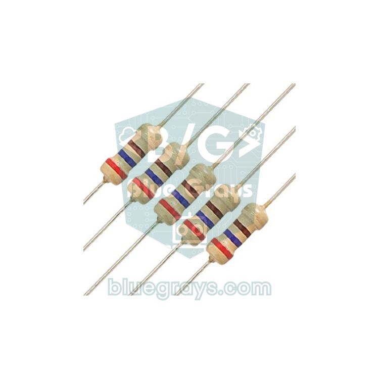
| LED resistor | Current (red LED, 5 V) | Uno R3 | Uno R4 |
|---|---|---|---|
| 220 Ω | ≈ 13.6 mA | Fine | Above the limit |
| 330 Ω | ≈ 9.1 mA | Fine | Slightly above the limit |
| 470 Ω | ≈ 6.4 mA | Fine | Fine |
| 1 kΩ | ≈ 3 mA | Fine | Fine, the LED is still clearly visible |
Do old sketches and libraries work on the R4?
Short answer: most do. Sketches written with standard Arduino commands such as digitalWrite, analogRead, millis, Serial, Wire (I2C), SPI, EEPROM, Servo and tone compile on the R4 without changes. Problems appear in code that talks directly to the ATmega328P hardware: fast pin operations with registers like PORTB and DDRD, Timer1 settings, header files starting with avr/ and the libraries that use them won't compile on the R4. For example, a sketch that uses PORTB fails with 'PORTB' was not declared in this scope.
| Library or code | Status on the R4 | Note |
|---|---|---|
| Servo, Wire, SPI, EEPROM, SoftwareSerial | Works | Official R4 support |
| Adafruit NeoPixel, FastLED | Works | Install the latest versions |
| DHT sensor library | Works | Adafruit library |
| IRremote | Partly works | 4.x versions can read an IR receiver on the R4; according to the library docs, sending does not work on the R4 WiFi |
| LiquidCrystal I2C, MFRC522 | Works, with a warning | The architecture warning is harmless |
| TimerOne | Doesn't compile | Use the FspTimer class from the board package instead |
| PORTB, DDRD, PIND registers | Doesn't compile | Use digitalWrite and digitalRead |
| serialEvent() | Never called | Check Serial.available() inside loop |
While compiling you may see a warning like WARNING: library LiquidCrystal I2C claims to run on avr architecture(s) and may be incompatible with your current board which runs on renesas_uno architecture(s). This isn't an error; the library's author simply listed only AVR as a supported architecture. If the sketch uploads and runs, you're fine. If you get a real error, first install the library's latest version (adding a library to Arduino); if that doesn't help, look for an alternative with R4 support.
There's one more difference to watch: the R3 has a single serial port, connected to both USB and pins D0/D1. On the R4, Serial is USB only, and pins D0 and D1 work separately as Serial1. An old sketch that reads a module such as an HC-05 Bluetooth or a GPS on D0/D1 through Serial will receive nothing on the R4. The bridge sketch below passes data from the module to the Serial Monitor and what you type in the Serial Monitor to the module:
1// R4'te Serial = USB, Serial1 = D0 (RX) ve D1 (TX) / on the R4, Serial = USB, Serial1 = D0 (RX) and D1 (TX)
2
3void setup() {
4  Serial.begin(115200);   // bilgisayar (Seri Monitör) / computer (Serial Monitor)
5  Serial1.begin(9600);    // D0/D1'e bağlı modül, örn. HC-05 / module on D0/D1, e.g. HC-05
6}
7
8void loop() {
9  if (Serial1.available()) {
10    Serial.write(Serial1.read());   // modülden bilgisayara / module to computer
11  }
12  if (Serial.available()) {
13    Serial1.write(Serial.read());   // bilgisayardan modüle / computer to module
14  }
15}Setting up the Uno R4 in the Arduino IDE
- Install or update Arduino IDE 2 (installing the Arduino IDE).
- Open the Boards Manager on the left, type UNO R4 and install the Arduino UNO R4 Boards package. It's an official package, so you don't need to add an extra URL.
- Connect the board with a USB-C cable that carries data and choose Arduino UNO R4 Minima or Arduino UNO R4 WiFi from Tools > Board.
- Pick the board's port from Tools > Port, open File > Examples > 01.Basics > Blink and upload it. The built-in LED on D13 starts blinking.
- If no port appears or the upload stops halfway, quickly press the RESET button twice: the board enters bootloader mode and the port shows up again. For all upload problems, see the Arduino won't upload guide.
Uno R4 WiFi: the ESP32-S3 and the 12x8 LED matrix
By default the R4 WiFi's ESP32-S3 runs firmware installed by Arduino that turns commands from the RA4M1 into Wi-Fi and Bluetooth operations. You still write your sketch for the RA4M1: you use the WiFiS3 library that comes with the board package for Wi-Fi and the ArduinoBLE library for Bluetooth. There are two important limits: the module only joins 2.4 GHz networks, and because Wi-Fi and Bluetooth share the antenna you can't use both at the same time. Some newer features need up-to-date ESP32-S3 firmware; you can update it from Tools > Firmware Updater in the IDE.
The matrix on the front of the board consists of 96 red LEDs in 8 rows and 12 columns. When it first comes out of the box, it plays a Tetris animation. The LEDs are wired to 11 internal pins of the RA4M1 using a technique called charlieplexing; those pins aren't brought out to the headers, so using the matrix doesn't cost you any of D0–D13 or A0–A5. The Arduino_LED_Matrix library in the board package accepts a frame in two formats: an 8x12 byte array or three 32-bit numbers. The array method is easier to read, because you can see the shape formed by the 1s right in the code:
1#include "Arduino_LED_Matrix.h"   // kart paketiyle gelir / ships with the board package
2
3ArduinoLEDMatrix matrix;
4
5// 8 satır x 12 sütun: 1 = LED yanar / 8 rows x 12 columns: 1 = LED on
6uint8_t kalp[8][12] = {
7  { 0, 0, 1, 1, 0, 0, 0, 1, 1, 0, 0, 0 },
8  { 0, 1, 0, 0, 1, 0, 1, 0, 0, 1, 0, 0 },
9  { 0, 1, 0, 0, 0, 1, 0, 0, 0, 1, 0, 0 },
10  { 0, 0, 1, 0, 0, 0, 0, 0, 1, 0, 0, 0 },
11  { 0, 0, 0, 1, 0, 0, 0, 1, 0, 0, 0, 0 },
12  { 0, 0, 0, 0, 1, 0, 1, 0, 0, 0, 0, 0 },
13  { 0, 0, 0, 0, 0, 1, 0, 0, 0, 0, 0, 0 },
14  { 0, 0, 0, 0, 0, 0, 0, 0, 0, 0, 0, 0 }
15};
16
17void setup() {
18  matrix.begin();
19}
20
21void loop() {
22  matrix.renderBitmap(kalp, 8, 12);          // kendi çizimin / your own drawing
23  delay(1000);
24  matrix.loadFrame(LEDMATRIX_EMOJI_HAPPY);   // kütüphanedeki hazır kare / ready-made frame from the library
25  delay(1000);
26  kalp[7][11] = 1;                           // tek bir LED'i yak: satır 7, sütun 11 / turn on one LED: row 7, column 11
27}
renderBitmap() shows the array you drew yourself, while loadFrame() loads ready-made frames from the library: LEDMATRIX_HEART_BIG, LEDMATRIX_EMOJI_HAPPY, LEDMATRIX_EMOJI_SAD and LEDMATRIX_DANGER are a few of them. With loadSequence() and play() you can run ready-made animations such as LEDMATRIX_ANIMATION_TETRIS or LEDMATRIX_ANIMATION_WIFI_SEARCH. To write and scroll text on the matrix, you need to install the ArduinoGraphics library from the Library Manager. If you want a bigger display, take a look at the MAX7219 LED matrix and WS2812B NeoPixel articles.
First project: controlling the LED matrix from your phone
Now let's combine the two features. While the board connects to your home network, the matrix plays a Wi-Fi search animation; once connected, it shows the IP address as scrolling text. When you open that address in the browser of a phone on the same network, buttons let you show a heart, a happy or a sad face, scroll the IP address again or switch the matrix off. You don't need any parts besides the board.
- Install the ArduinoGraphics library from the Library Manager; WiFiS3 and Arduino_LED_Matrix come with the board package.
- Replace the network name and password in the sketch with your own; watch upper and lower case.
- Select Arduino UNO R4 WiFi as the board, upload the sketch and open the Serial Monitor at 115200 baud.
- Type the IP address scrolling on the matrix or printed in the Serial Monitor into your phone's browser.
- Tap the buttons on the page; the matrix changes instantly.
1#include "ArduinoGraphics.h"      // Arduino_LED_Matrix'ten ÖNCE eklenmeli / must come BEFORE Arduino_LED_Matrix
2#include "Arduino_LED_Matrix.h"
3#include "WiFiS3.h"
4
5char ssid[] = "AgAdi";            // Wi-Fi adın / your Wi-Fi name
6char pass[] = "Sifre123";         // Wi-Fi şifren / your Wi-Fi password
7
8ArduinoLEDMatrix matrix;
9WiFiServer server(80);
10
11void scrollText(String text) {
12  matrix.beginDraw();
13  matrix.stroke(0xFFFFFFFF);
14  matrix.textScrollSpeed(60);             // her adım 60 ms / 60 ms per step
15  matrix.textFont(Font_5x7);
16  matrix.beginText(0, 1, 0xFFFFFF);
17  matrix.print("   " + text + "   ");
18  matrix.endText(SCROLL_LEFT);            // yazıyı sola kaydır / scroll the text to the left
19  matrix.endDraw();
20}
21
22void sendPage(WiFiClient &client) {
23  client.println("HTTP/1.1 200 OK");
24  client.println("Content-Type: text/html; charset=utf-8");
25  client.println("Connection: close");
26  client.println();
27  client.println("<!DOCTYPE html><html><head><meta name='viewport' content='width=device-width'></head><body>");
28  client.println("<h2>UNO R4 WiFi</h2>");
29  client.println("<p><a href='/kalp'><button>Kalp / Heart</button></a></p>");
30  client.println("<p><a href='/mutlu'><button>Mutlu / Happy</button></a></p>");
31  client.println("<p><a href='/uzgun'><button>Uzgun / Sad</button></a></p>");
32  client.println("<p><a href='/ip'><button>IP</button></a></p>");
33  client.println("<p><a href='/kapat'><button>Kapat / Off</button></a></p>");
34  client.println("</body></html>");
35}
36
37void setup() {
38  Serial.begin(115200);
39  matrix.begin();
40
41  if (WiFi.status() == WL_NO_MODULE) {               // ESP32-S3 yanıt vermiyor / ESP32-S3 not responding
42    Serial.println("WiFi modulu bulunamadi / WiFi module not found");
43    matrix.loadFrame(LEDMATRIX_DANGER);
44    while (true) {}
45  }
46
47  matrix.loadSequence(LEDMATRIX_ANIMATION_WIFI_SEARCH);   // bağlanırken animasyon / animation while connecting
48  matrix.play(true);
49
50  while (WiFi.begin(ssid, pass) != WL_CONNECTED) {
51    Serial.println("Baglaniyor / connecting...");
52    delay(5000);
53  }
54  while (WiFi.localIP() == IPAddress(0, 0, 0, 0)) {   // DHCP adresini bekle / wait for the DHCP address
55    delay(100);
56  }
57
58  server.begin();
59  Serial.print("IP: ");
60  Serial.println(WiFi.localIP());
61  scrollText(WiFi.localIP().toString());     // IP adresini matriste göster / show the IP on the matrix
62  matrix.loadFrame(LEDMATRIX_EMOJI_HAPPY);
63}
64
65void loop() {
66  WiFiClient client = server.available();
67  if (!client) {
68    return;
69  }
70
71  String request = client.readStringUntil('\n');   // ör. "GET /kalp HTTP/1.1" / e.g. "GET /kalp HTTP/1.1"
72  while (client.available()) {
73    client.read();                                 // kalan başlıkları at / discard the remaining headers
74  }
75
76  bool showIp = false;
77  if (request.indexOf("GET /kalp") >= 0) {
78    matrix.loadFrame(LEDMATRIX_HEART_BIG);
79  } else if (request.indexOf("GET /mutlu") >= 0) {
80    matrix.loadFrame(LEDMATRIX_EMOJI_HAPPY);
81  } else if (request.indexOf("GET /uzgun") >= 0) {
82    matrix.loadFrame(LEDMATRIX_EMOJI_SAD);
83  } else if (request.indexOf("GET /kapat") >= 0) {
84    matrix.clear();
85  } else if (request.indexOf("GET /ip") >= 0) {
86    showIp = true;
87  }
88
89  sendPage(client);
90  delay(10);
91  client.stop();                                   // bağlantıyı kapat / close the connection
92
93  if (showIp) {
94    scrollText(WiFi.localIP().toString());         // sayfa gittikten sonra kaydır / scroll after the page is sent
95  }
96}
The logic is simple: WiFi.begin() is retried until the connection is up, then the sketch waits for DHCP to hand out an IP address and starts a web server on port 80. It reads the first line of the request from the phone (for example "GET /kalp HTTP/1.1"), uses indexOf() to work out which button was pressed and loads the matching frame onto the matrix. endText(SCROLL_LEFT) blocks the program while the text scrolls, which is why we scroll the IP address again only after sending the page and closing the connection. If the matrix shows the danger symbol and stops, the ESP32-S3 isn't responding; unplug and replug the board's USB cable and update the firmware. If the connection never comes up, the 2.4 GHz and password checks from the ESP32 won't connect to Wi-Fi article apply here too.
Power supply: VIN, 5V and 3.3 V pins
The R4 accepts 6–24 V on the DC jack or the VIN pin; the onboard buck converter steps it down to 5 V. According to Arduino's R4 WiFi documentation, about 1.2 A can be drawn from the 5V pin when the board is powered from VIN; on USB power the board itself handles up to 2 A, but the real limit is set by your computer's USB port. That current is meant for sensors and small modules, not motors and servos. The Minima's 3.3 V pin is fed by the RA4M1's internal regulator, so it's only good for small sensors; don't power high-current modules such as an ESP-01 or an nRF24L01 with a PA+LNA antenna from it. The R4 WiFi also has an OFF pin (connecting it to GND cuts the board's 5 V supply) and a VRTC pin for the RTC battery. For every power option, see How to power an Arduino.
Project ideas with the Uno R4
- Wi-Fi weather station: show the temperature measured with a DHT11 both as scrolling text on the matrix and on a page you open on your phone.
- Matrix games: snake, Tetris or a bouncing ball on the 12x8 matrix; for more ideas, see the Arduino game projects article.
- Internet clock: get the time from the internet (NTP), write it to the built-in RTC and keep it through power cuts with a battery on the VRTC pin.
- USB macro keypad: build a keypad with four buttons that triggers shortcuts on your computer; thanks to the R4's HID support, you don't need a Leonardo.
- Sound with the DAC: generate a sine wave on A0 with the analogWave library and build a simple synthesizer with an audio amplifier and a speaker.
- Lamp control from your phone: combine the web server from this article with a relay module and switch a lamp on remotely.
Common mistakes and how to fix them
| Symptom | Cause | Fix |
|---|---|---|
| 'PORTB' was not declared in this scope | The code uses AVR registers directly | Rewrite it with digitalWrite and digitalRead |
| 'class TimerOne' has no member named 'initialize' | TimerOne only knows the AVR timers | Use the FspTimer class from the board package |
| 'class ArduinoLEDMatrix' has no member named 'beginDraw' | ArduinoGraphics is missing or included after the matrix library | Install ArduinoGraphics and include it before Arduino_LED_Matrix |
| Errors like 'D24' was not declared inside WiFiS3 files | The R4 Minima is selected as the board | Select the R4 WiFi from Tools > Board |
| No data from the module on D0/D1 | On the R4, Serial is USB only | Use Serial1 instead of Serial |
| No port, or the upload stops halfway | The running sketch locked up USB, or the cable is charge-only | Press RESET twice and use a data cable |
| A pin stopped working | The pin was pushed beyond the 8 mA limit | Use 470 Ω–1 kΩ for LEDs and drive big loads through a transistor |
| A sensor on the Qwiic connector isn't found | Qwiic is wired to the second I2C bus (Wire1) | Use Wire1 instead of Wire in your code |
Which one should you buy: R3, R4 Minima or R4 WiFi?
- Uno R4 WiFi: the best choice if your projects will connect to the internet, a phone or Bluetooth, and you want a ready-made display on the board. It's fun for beginners too, because you immediately see your code working on the matrix.
- Uno R4 Minima: a good fit if you don't need wireless and want more memory, speed, a DAC and USB-C. Thanks to its SWD connector, it's also a good option if you want to attach an external debugger and step through your code.
- Uno R3 or a compatible clone: still makes sense if you have old projects that use AVR-specific libraries, want to follow textbook examples exactly, or are looking for the lowest cost; its pins handle 20 mA comfortably.
- ESP32: if you want Wi-Fi with more pins at a lower price, an ESP32 board is worth considering too; just remember that it runs at 3.3 V (Arduino or ESP32?).
In short, the Uno R4 is an upgrade that keeps the Uno's familiar ease of use and adds memory, speed and new hardware; just keep the 8 mA limit and the Serial1 difference in mind. To get to know the board's pins in detail, take a look at the Arduino Uno pinout article. In the BlueGrays app you'll find LED, button, sensor, LCD and LED matrix projects for the Arduino Uno with step-by-step circuit diagrams and code; these projects are written with standard commands, so they run on the R4 too, and all you need to do is raise the LED resistors to 470 Ω.
Frequently asked questions
What is the difference between the Arduino Uno R4 and R3?
Instead of the R3's 8-bit, 16 MHz ATmega328P, the Uno R4 uses a 32-bit Renesas RA4M1 running at 48 MHz. Flash grows from 32 KB to 256 KB and SRAM from 2 KB to 32 KB, and it adds a 12-bit DAC, a 14-bit ADC, CAN, an RTC, USB-C and USB keyboard and mouse support. The board size, pin layout and 5 V operating voltage stay the same.
Do Arduino Uno R3 sketches work on the R4?
Most sketches and libraries written with standard Arduino commands work without changes. Code that directly accesses AVR registers such as PORTB, Timer1 settings or avr/ header files won't compile. Also, in sketches that read modules connected to D0/D1, you need to write Serial1 instead of Serial.
Should I buy the Arduino Uno R4 WiFi or the Minima?
Get the R4 WiFi if your projects need Wi-Fi, Bluetooth or control from a phone; the built-in LED matrix and Qwiic connector are a bonus. If you don't need wireless, the Minima is cheaper and gives the same performance with the same processor.
How much current can an Arduino Uno R4 pin supply?
Arduino recommends drawing no more than 8 mA per pin on the Uno R4, compared with 20 mA on the R3. That's why you should use at least 470 Ω instead of 220 Ω for LEDs and drive loads such as relays, motors and buzzers through a transistor or MOSFET.
Do Arduino R3 shields fit the Uno R4?
Yes. The R4 Minima and R4 WiFi have the same board size, header layout and 5 V logic level as the R3, so most motor driver, relay and sensor shields plug straight in. You may only need a software update if the shield's library contains AVR-specific code.
Does the Arduino Uno R4 WiFi support Bluetooth?
Yes, the onboard ESP32-S3 module supports Bluetooth 5 LE and is used with the ArduinoBLE library. However, Wi-Fi and Bluetooth share the same antenna, so they can't run at the same time. Classic Bluetooth serial connections like the HC-05's aren't supported; your phone app has to use BLE.
Projects to build after reading this
See all projects
LED Blink
The very first hello of electronics: switching a single LED on and off. The Arduino turns the LED on and off at short intervals, so the light blinks quickly. You see in the simplest way how the board

Traffic Light
A tiny copy of the traffic light you see on the road every day. Red stays on for two seconds, yellow flashes for a moment, green stays on for two seconds, then it goes back to red through yellow again

LED Control with a Push Button (Push)
Just like a doorbell: the light stays on as long as you press, and goes off when you let go. The Arduino keeps listening to the button; while it's pressed the LED is on, and the moment you lift your f
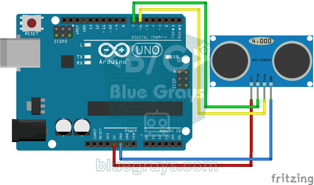
HC-SR04 Distance Measurement (Serial Display)
The HC-SR04 sensor works just like a bat finding its way in the dark: it sends out a sound you cannot hear, listens for the echo and measures how far away the object in front of it is. The Arduino wri
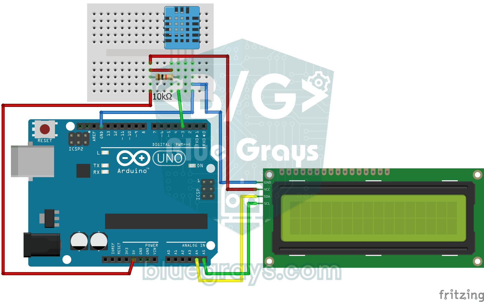
Temperature and Humidity with DHT11
How warm is your room, and is the air humid or dry? The DHT11 sensor measures temperature and humidity, and the Arduino writes the values on a two-line LCD screen, refreshing every couple of seconds.

Dot Matrix Clock and Calendar (MAX7219, DS1307)
A glowing board for your desk or wall that shows the time and date in scrolling text. The 8x32 LED display holds a big-digit clock whose two dots blink every second; at the start of each minute the da

Pixel Snake 8x8 Matrix
Build the classic snake game with your own hands and play it. On a colorful 8x8 light matrix, you steer a green snake with a joystick and eat red apples; with every apple the snake grows, speeds up a

4x 32x8 Matrix LED Animation and Text
Stack four long LED matrix modules on top of each other and you get a square screen with more than a thousand dots of light. First, letters pour down from the top like rain in the movies, then a curta