
Winter Break Arduino Projects: A 14-Day Step-by-Step Plan
Winter break Arduino projects in a 14-day plan: one project a day with a starter kit, three paths for Uno, ESP32 and Pico, a parts list and a final project.
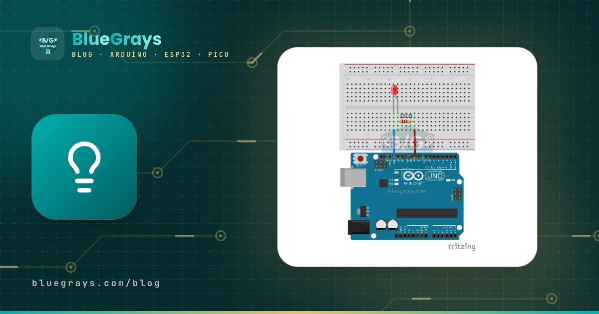
The best way to approach winter break Arduino projects is to spend two weeks on small projects that each build on the last one, instead of random experiments. In this guide you'll find a ready-made plan: working 1–2 hours a day with a starter kit, in 14 days you'll go from lighting an LED to reading sensors, from writing on a screen to driving a motor. Each day's project, the parts you need and a link to an in-depth post on the topic are listed one by one; by the end of the break you'll have a final project that combines everything you've learned.
The plan can be adapted to three paths: the Arduino Uno for people with no experience, the ESP32 for those with basic knowledge who want to connect their project to the internet, and the Raspberry Pi Pico for those who want to learn Python. The daily topics are the same on all three paths; only the board, pin numbers and programming language change. If you don't have a board yet, you can do the first days in a Wokwi or Tinkercad simulation and move to the real circuit when your parts arrive.
Before you start: what parts do you need?
Almost everything on the list below comes in standard starter kits. If your kit is missing something, just rearrange the order of the days; for example, if you have no servo, you can swap day 13 for a buzzer melody project. If you can't decide which kit to buy, the Arduino starter kit post compares the contents in detail.
| Part | Qty | Days used |
|---|---|---|
| Arduino Uno, ESP32 or Raspberry Pi Pico + USB cable | 1 | Every day |
| Breadboard and male-to-male jumper wires | 1 + 30 | Every day |
| LED (red, yellow, green) | 6–8 | 1, 2, 3, 6, 7, 9, 11 |
| 220 Ω resistor | 8 | 1, 2, 3, 6, 7, 11 |
| 10 kΩ resistor | 2 | 7 |
| 1 kΩ resistor (voltage divider for ESP32 and Pico) | 3 | 10, 11 |
| Push button | 2 | 4, 7, 9 |
| 10 kΩ potentiometer | 1 | 5, 13 |
| RGB LED | 1 | 6 |
| LDR | 1 | 7 |
| Passive buzzer | 1 | 8, 11 |
| HC-SR04 distance sensor | 1 | 10, 11 |
| DHT11 temperature and humidity sensor | 1 | 12 |
| I2C 16x2 LCD display | 1 | 12, 14 |
| SG90 servo motor | 1 | 13, 14 |
Which path should you choose: Uno, ESP32 or Pico?
All three boards can do this entire plan, but each offers a different learning experience. The Uno runs at 5 V, so it connects directly to every module in the kit, and most examples on the internet are written for it; if this is your first time with electronics, it's the easiest path for debugging. The ESP32 is programmed in the same Arduino language, but its 240 MHz dual-core processor, Wi-Fi and Bluetooth let you monitor your final project from your phone; in return, you have to remember its pins are 3.3 V. The Pico lets you write code in MicroPython and see it run the moment you save it; if you study Python at school, you carry that knowledge straight onto hardware. If you can't decide, take a look at the Arduino vs ESP32 comparison.
| Path | Who it's for | Language and editor | Strengths | What to watch out for |
|---|---|---|---|---|
| Arduino Uno | People new to electronics | Arduino C++, Arduino IDE | 5 V pins, works directly with every module in the kit, the most example code | No Wi-Fi, only 2 KB of RAM |
| ESP32 | People who know the basics and want to connect to the internet | Arduino C++, Arduino IDE (ESP32 board package) | Wi-Fi and Bluetooth, 240 MHz dual core, 12-bit ADC | 3.3 V pins; sensors with 5 V signals need a voltage divider |
| Raspberry Pi Pico | People who want to learn Python | MicroPython, Thonny | Runs instantly with no compile wait, 133 MHz dual core, low price | 3.3 V pins; the classic Pico has no wireless (the Pico W does) |
Daily routine: the 1–2 hour rule
- First 15 minutes, reading: Read the post given for that day and draw the circuit diagram and pin table on paper.
- 30–45 minutes, build and code: Build the circuit with the USB cable unplugged, check the connections once more, then upload the code.
- 20 minutes, modify: Once the code works, change at least one thing yourself: the delay, the pin, the threshold value or the number of LEDs. This is where the real learning happens.
- 10 minutes, notes: Write in a notebook what you did, where you got stuck and how you solved it; these notes will save you a lot of time on the final project.
- Flexible days: If you get sick or a project runs long, you can use days 7 and 14 as catch-up days.
Week 1: the basics (days 1–7)
The goal of the first week is to learn four core concepts hands-on: digital output, digital input, analog reading and PWM. Each day adds about one new command and one new part; by the end of day 7 you'll be comfortable with pinMode, digitalWrite, digitalRead, analogRead, analogWrite and Serial.println.
- Day 1 – Lighting an LED: Run Blink with the board's built-in LED, then connect an external LED to D13 through a 220 Ω resistor on the breadboard and change the blink time. Parts: board, breadboard, 1 LED, 1 × 220 Ω resistor. Read: How to use a breadboard, Calculating the LED resistor.
- Day 2 – Traffic light: Connect red, yellow and green LEDs to D10, D9 and D8 and use delay to imitate the light sequence at a real intersection. Parts: 3 LEDs, 3 × 220 Ω resistors. Read: Arduino traffic light.
- Day 3 – Chasing LEDs and Knight Rider: Learn to use a for loop and a pin array while lighting 6 LEDs in sequence. Parts: 6 LEDs, 6 × 220 Ω resistors. Read: Knight Rider and chasing LEDs, Using arrays in Arduino.
- Day 4 – LED with a button: First make an LED that stays on while you hold the button, then one that toggles with every press; you'll learn INPUT_PULLUP and debouncing here. Parts: 1 button, 1 LED, 1 × 220 Ω resistor. Read: How to connect a button to Arduino, Pull-up and pull-down resistors.
- Day 5 – Potentiometer and Serial Monitor: Read values from 0–1023 with analogRead, watch them in the Serial Monitor and use map to turn the value into the LED's blink speed. Parts: 10 kΩ potentiometer, 1 LED. Read: What is a potentiometer, Using the Serial Monitor, The map function.
- Day 6 – PWM and the RGB LED: Fade an LED slowly in and out with analogWrite (a breathing effect), then mix the three channels of the RGB LED to create your own colour. Parts: 1 RGB LED, 3 × 220 Ω resistors. Read: What is PWM, Using an RGB LED.
- Day 7 – LDR night light and weekly review: Connect the LDR with a 10 kΩ resistor as a voltage divider and turn on the LED when the room gets dark. In the second half of the day, build the traffic light with a pedestrian button below. Parts: LDR, 10 kΩ resistor, 3 LEDs, button. Read: LDR light sensor, Voltage divider.
The closing project of week 1 combines what you learned on days 2, 4 and 5 in one circuit: a traffic light that stays green for cars; when a pedestrian presses the button it switches to yellow, then red, and returns to green after five seconds. The button connects between D2 and GND; thanks to the internal pull-up resistor you don't need an external one, and the pin reads LOW when the button is pressed.
1// Yaya butonlu trafik lambası / Pedestrian button traffic light
2const int RED_PIN = 10;      // kırmızı LED / red LED
3const int YELLOW_PIN = 9;    // sarı LED / yellow LED
4const int GREEN_PIN = 8;     // yeşil LED / green LED
5const int BUTTON_PIN = 2;    // buton, diğer ucu GND / button, other leg to GND
6
7void setup() {
8  pinMode(RED_PIN, OUTPUT);
9  pinMode(YELLOW_PIN, OUTPUT);
10  pinMode(GREEN_PIN, OUTPUT);
11  pinMode(BUTTON_PIN, INPUT_PULLUP);   // basılınca LOW okunur / reads LOW when pressed
12  digitalWrite(GREEN_PIN, HIGH);       // araçlara yeşil / green for cars
13  Serial.begin(9600);
14}
15
16void loop() {
17  if (digitalRead(BUTTON_PIN) == LOW) {
18    Serial.println("Yaya istegi / Pedestrian request");
19    delay(1000);
20    digitalWrite(GREEN_PIN, LOW);
21    digitalWrite(YELLOW_PIN, HIGH);    // sarı: yavaşla / yellow: slow down
22    delay(2000);
23    digitalWrite(YELLOW_PIN, LOW);
24    digitalWrite(RED_PIN, HIGH);       // araçlar durur, yaya geçer / cars stop, pedestrians cross
25    delay(5000);
26    digitalWrite(YELLOW_PIN, HIGH);    // kırmızı + sarı: hazırlan / red + yellow: get ready
27    delay(1500);
28    digitalWrite(RED_PIN, LOW);
29    digitalWrite(YELLOW_PIN, LOW);
30    digitalWrite(GREEN_PIN, HIGH);
31    delay(3000);                       // art arda basmayı engelle / ignore repeated presses
32  }
33}
The final delay(3000) in the code stops the light from turning red again straight away if a pedestrian presses the button repeatedly; real traffic lights use a similar waiting time. For your own modification, try making the red time adjustable with a potentiometer, or making the buzzer play short beeps while the light is red. The weakness of this code is that the board can't do anything else while delay is running; on day 9 you'll solve this with millis.
Week 2: sound, timing, sensors and display (days 8–14)
In the second week the board starts measuring the outside world and showing the results. In these days you'll install a library for the first time, measure time with microsecond precision and write text on a display. Because the projects are a bit longer, don't hesitate to split a day into two if needed; the plan isn't a race, it's a way to build a habit.
- Day 8 – Buzzer and melody: Play notes with tone(pin, frequency, duration); 262 Hz is C, 294 Hz is D, 330 Hz is E. An active buzzer gives one fixed tone; for melodies you need a passive buzzer. Parts: passive buzzer. Read: What is a buzzer.
- Day 9 – millis instead of delay: Manage to read the button while an LED blinks once a second. This is the foundation of the final project; every project that does several things at once uses millis or a state machine. Parts: 2 LEDs, button. Read: millis vs delay, Arduino state machine.
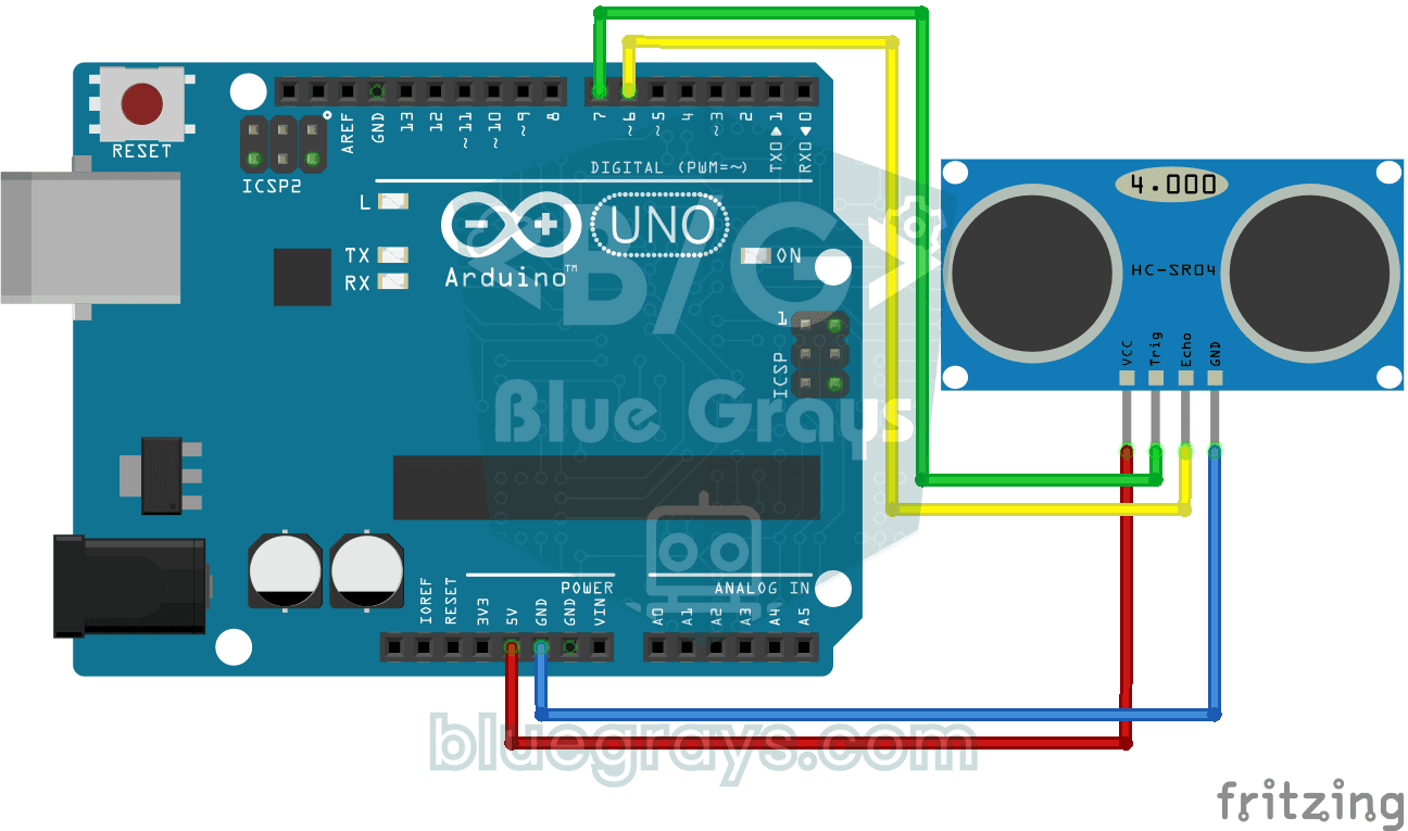
- Day 10 – Measuring distance with the HC-SR04: Measure the time a sound wave takes to travel out and back; since sound moves through air at about 343 m/s, dividing the time in microseconds by 58 gives the distance in centimetres. Parts: HC-SR04. Read: HC-SR04 distance sensor.
- Day 11 – Parking sensor: Combine days 8 and 10: the closer an obstacle gets, the shorter the buzzer's beep interval, and the LED flashes with every beep. Parts: HC-SR04, passive buzzer, LED, 220 Ω resistor. Read: Arduino parking system.
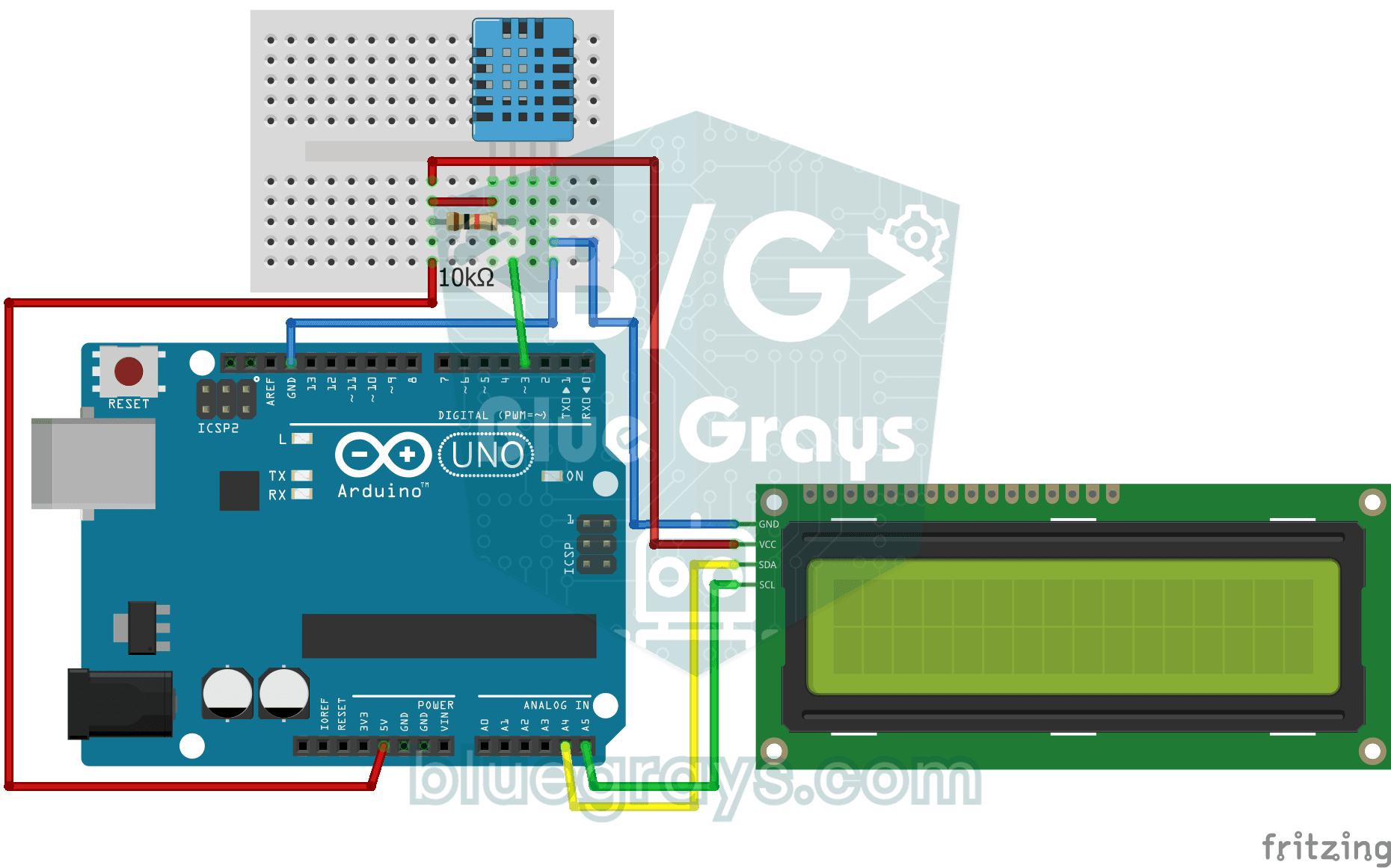
- Day 12 – DHT11 and I2C LCD: Install your first library and write temperature and humidity on a 16x2 LCD. Thanks to I2C the display connects with only 4 wires; most modules have the address 0x27 or 0x3F. Parts: DHT11, I2C 16x2 LCD. Read: Adding an Arduino library, DHT11 sensor, I2C LCD display.
- Day 13 – Servo motor and final plan: Turn the SG90 between 0 and 180 degrees with the Servo library and control the angle with a potentiometer. In the second half of the day, pick your final project and put your plan on paper using the steps below. Parts: SG90 servo, potentiometer. Read: What is a servo motor, Servo jitter problem.
- Day 14 – Final project and presentation: Combine the code from the previous days, place the circuit in a box or a cardboard model, film a short video and present your project to your family or class. Parts: the final project's parts list. Read: Science fair project presentation.
The code below is the day 11 parking sensor and reuses the distance measuring method you learned on day 10 inside a function. The 30,000-microsecond timeout in pulseIn corresponds to about 5 metres; if the sensor gets no echo, the code returns -1 instead of waiting forever. The map function converts the 0–50 cm range into a 50–500 ms pause, so the beeps get more frequent as the obstacle gets closer.
1// Park sensörü: HC-SR04 + buzzer + LED / Parking sensor: HC-SR04 + buzzer + LED
2const int TRIG_PIN = 7;
3const int ECHO_PIN = 6;
4const int BUZZER_PIN = 5;    // pasif buzzer / passive buzzer
5const int LED_PIN = 4;       // 220 ohm dirençle / with a 220 ohm resistor
6
7long readDistanceCm() {
8  digitalWrite(TRIG_PIN, LOW);
9  delayMicroseconds(2);
10  digitalWrite(TRIG_PIN, HIGH);     // 10 mikrosaniye tetik darbesi / 10 microsecond trigger pulse
11  delayMicroseconds(10);
12  digitalWrite(TRIG_PIN, LOW);
13  unsigned long duration = pulseIn(ECHO_PIN, HIGH, 30000UL);  // 30 ms zaman aşımı / 30 ms timeout
14  if (duration == 0) return -1;     // yankı yok / no echo
15  return duration / 58;             // mikrosaniye -> cm / microseconds -> cm
16}
17
18void setup() {
19  pinMode(TRIG_PIN, OUTPUT);
20  pinMode(ECHO_PIN, INPUT);
21  pinMode(BUZZER_PIN, OUTPUT);
22  pinMode(LED_PIN, OUTPUT);
23  Serial.begin(9600);
24}
25
26void loop() {
27  long cm = readDistanceCm();
28  Serial.print("Mesafe / Distance: ");
29  Serial.print(cm);
30  Serial.println(" cm");
31
32  if (cm > 0 && cm < 50) {
33    int pause = map(cm, 0, 50, 50, 500);   // yaklaştıkça kısalır / shorter when closer
34    tone(BUZZER_PIN, 2000, 50);            // 2 kHz, 50 ms bip / 2 kHz, 50 ms beep
35    digitalWrite(LED_PIN, HIGH);
36    delay(50);
37    digitalWrite(LED_PIN, LOW);
38    delay(pause);
39  } else {
40    noTone(BUZZER_PIN);
41    digitalWrite(LED_PIN, LOW);
42    delay(200);
43  }
44}| Connection | Arduino Uno | ESP32 | Raspberry Pi Pico |
|---|---|---|---|
| HC-SR04 VCC | 5V | VIN / 5V | VBUS (5 V) |
| HC-SR04 GND | GND | GND | GND |
| HC-SR04 TRIG | D7 | GPIO 5 | GP14 |
| HC-SR04 ECHO | D6 | GPIO 18 (via voltage divider) | GP15 (via voltage divider) |
| Buzzer (+) | D5 | GPIO 19 | GP13 |
| LED (with 220 Ω) | D4 | GPIO 23 | GP12 |
ESP32 path: the same plan, with Wi-Fi added
If you're following the ESP32 path, you do days 1–13 with almost the same code; you only change the pin numbers. There are two differences to watch out for: analogRead on the ESP32 returns values from 0–4095 (12 bit), and for analog reading you should prefer ADC1 pins (GPIO 32–39), because ADC2 pins can't be used while Wi-Fi is on. Besides that, set aside one evening after day 9 for Wi-Fi: the code below shows the distance measured by the parking sensor on a web page on your local network; the page refreshes itself every second and the LED lights when the distance falls below 30 cm. If you leave the buzzer connected to GPIO 19 as in the table, adding an audible warning to the final becomes easy too. For setting up the board, see the What is ESP32 post.
1#include <WiFi.h>
2#include <WebServer.h>
3
4const char* WIFI_SSID = "AgAdi";      // kendi ağ adın / your network name
5const char* WIFI_PASS = "Sifre123";   // kendi şifren / your password
6
7const int TRIG_PIN = 5;
8const int ECHO_PIN = 18;   // gerilim bölücüyle / through a voltage divider
9const int LED_PIN = 23;
10
11WebServer server(80);
12
13long readDistanceCm() {
14  digitalWrite(TRIG_PIN, LOW);
15  delayMicroseconds(2);
16  digitalWrite(TRIG_PIN, HIGH);
17  delayMicroseconds(10);
18  digitalWrite(TRIG_PIN, LOW);
19  unsigned long duration = pulseIn(ECHO_PIN, HIGH, 30000UL);  // 30 ms zaman aşımı / 30 ms timeout
20  if (duration == 0) return -1;
21  return duration / 58;
22}
23
24void handleRoot() {
25  long cm = readDistanceCm();
26  digitalWrite(LED_PIN, (cm > 0 && cm < 30) ? HIGH : LOW);   // 30 cm altında uyarı / warn below 30 cm
27  String html = "<html><head><meta charset='utf-8'><meta http-equiv='refresh' content='1'></head><body>";
28  html += "<h1>Mesafe: " + String(cm) + " cm</h1></body></html>";
29  server.send(200, "text/html", html);
30}
31
32void setup() {
33  Serial.begin(115200);
34  pinMode(TRIG_PIN, OUTPUT);
35  pinMode(ECHO_PIN, INPUT);
36  pinMode(LED_PIN, OUTPUT);
37  WiFi.mode(WIFI_STA);
38  WiFi.begin(WIFI_SSID, WIFI_PASS);
39  while (WiFi.status() != WL_CONNECTED) {   // bağlanana kadar bekle / wait until connected
40    delay(500);
41    Serial.print(".");
42  }
43  Serial.println();
44  Serial.print("IP: ");
45  Serial.println(WiFi.localIP());            // bu adresi tarayıcıya yaz / type this address in a browser
46  server.on("/", handleRoot);
47  server.begin();
48}
49
50void loop() {
51  server.handleClient();
52}
After uploading the code, open the Serial Monitor at 115200 baud; once it connects, type the IP address it prints into your phone's browser. Your phone and the ESP32 must be on the same Wi-Fi network. The ESP32 only connects to 2.4 GHz networks; if it won't connect, follow the checklist in the ESP32 Wi-Fi not connecting post. Adding DHT11 data and an LED on/off link to this page in your final project would be a good goal for the next step.
Raspberry Pi Pico path: the same days with MicroPython
On the Pico path you use the Thonny editor instead of the Arduino IDE; after installing MicroPython on the Pico once, your code goes to the board the moment you save and run it. The built-in LED is on GP25 on the classic Pico (on the Pico W you access it with Pin("LED")), you use machine.PWM for PWM and machine.ADC for analog reading, and read_u16 returns a value in the 0–65535 range. If Python syntax is new to you, have a look at the MicroPython basics post before day 1; for an introduction to the board there's the What is Raspberry Pi Pico guide. The code below is the MicroPython version of the day 11 parking sensor and uses the Pico column in the pin table.
1from machine import Pin, PWM, time_pulse_us
2import time
3
4trig = Pin(14, Pin.OUT)
5echo = Pin(15, Pin.IN)          # gerilim bölücüyle / through a voltage divider
6buzzer = PWM(Pin(13))           # pasif buzzer / passive buzzer
7led = Pin(12, Pin.OUT)
8
9def mesafe_cm():
10    trig.value(0)
11    time.sleep_us(2)
12    trig.value(1)
13    time.sleep_us(10)            # 10 mikrosaniye tetik / 10 microsecond trigger
14    trig.value(0)
15    sure = time_pulse_us(echo, 1, 30000)   # 30 ms zaman aşımı / 30 ms timeout
16    if sure < 0:
17        return -1                # yankı yok / no echo
18    return sure / 58
19
20while True:
21    cm = mesafe_cm()
22    print("Mesafe / Distance:", cm, "cm")
23    if 0 < cm < 50:
24        bekle = int(50 + cm * 9)         # yaklaştıkça kısalır / shorter when closer
25        buzzer.freq(2000)
26        buzzer.duty_u16(32768)           # yüzde 50 doluluk / 50 percent duty
27        led.value(1)
28        time.sleep_ms(50)
29        buzzer.duty_u16(0)
30        led.value(0)
31        time.sleep_ms(bekle)
32    else:
33        buzzer.duty_u16(0)
34        led.value(0)
35        time.sleep_ms(200)
Final project: what will you finish at the end of the break?
The final project gathers the pieces you learned over two weeks into one useful device. A good final project should have at least one input (a sensor or button), one process (code that makes decisions) and one output (an LED, sound, display or motor). None of the options below needs an expensive part beyond the kit; pick the one that suits your level and work on it from day 13. For more ideas, check the Arduino project ideas list.
| Level / path | Final project | Days it combines | Extra parts |
|---|---|---|---|
| Uno – beginner | Smart parking assistant: beeps that speed up with distance, centimetres on the LCD, a servo barrier that lowers at 10 cm | 4, 9, 10, 11, 12, 13 | None, the kit is enough |
| Uno – alternative | Mini weather station: DHT11 data on the LCD, a button changes pages, the display backlight turns off in the dark | 4, 7, 9, 12 | None, the kit is enough |
| ESP32 | Room station monitored from your phone: temperature, humidity and distance on a web page, an LED switched on and off from the browser | 6, 9, 10, 12 + Wi-Fi | None, the ESP32 board is enough |
| Pico | Reaction game: whoever presses fastest when an LED lights at a random moment wins, the time shows in the Thonny console, the winner is celebrated with a buzzer melody | 4, 8, 9 | A second button |
- Describe it in one sentence: Write what the device will do in one clear sentence, like "As the car gets closer to the garage the beeping speeds up, and the barrier lowers at 10 cm."
- Draw an input-process-output diagram: Draw on paper, with boxes, which sensor will give data, what the code will decide and which part will react.
- Make a pin plan: Write in a table which pin each part connects to. Put outputs that need PWM, like LED brightness, on pins marked with ~; remember that on the Uno the Servo library disables PWM on D9 and D10. The pinout diagram tool makes it easier to find your board's pin map.
- Test piece by piece: Run each module on its own with its own small code first; don't move on to combining until they all work separately.
- Combine and clean up the delays: Put the code in a single file and replace long delays with the millis structure you learned on day 9, so that sensor reading, sound and the display don't wait for each other.
- Box it and present it: Place the circuit in a cardboard or plastic box, tape down the wires and film a 30–60 second demo video. If you want to make the circuit permanent, soldering onto perfboard could be your next step.
Where you often get stuck, and how to fix it
| Problem | Likely cause | Fix |
|---|---|---|
| Code won't upload, port not showing | Wrong board or port selected, missing CH340 driver, or a charge-only cable | Select the board and port in the Tools menu, use a data-capable USB cable, install the driver |
| LED doesn't light at all | LED is backwards, or its legs aren't in the same breadboard row | The long leg (anode) goes to the pin side, the short leg (cathode) to the GND side; try shifting the connection one row |
| Button triggers without being pressed | Pin is floating, no pull-up resistor | Use pinMode(pin, INPUT_PULLUP) and connect the other leg of the button to GND |
| HC-SR04 constantly shows 0 or -1 | TRIG and ECHO swapped, or the sensor isn't getting 5 V | Check the pin table, connect VCC to 5 V, point the sensor at a flat surface at least 2 cm away |
| LCD backlight is on but there's no text | Wrong contrast setting or I2C address | Turn the blue trimpot on the back of the module, try the addresses 0x27 and 0x3F |
| Board resets when the servo moves | The servo draws more current than USB can supply | Power the servo from an external 5 V supply and connect the supply's GND to the board's GND |
| "Failed to connect" error when uploading to the ESP32 | The board doesn't enter download mode | Hold the BOOT button when the upload starts, release it once "Connecting..." appears |
After two weeks you'll have not just a working final project but also a method for learning any new sensor or module on your own: read, draw, build, test, change. If you keep this habit going with one project a week once school starts, by summer you'll be ready for a science-fair-level project; the TÜBİTAK Arduino project ideas post is a good start for the idea stage. You can find step-by-step circuit diagrams and code for the plan's LED, traffic light, button, LDR night light, distance measuring and DHT11 projects for Uno, ESP32 and Pico in the BlueGrays app, and follow every day through the app.
Frequently asked questions
Can you learn Arduino during winter break?
Yes. Working 1–2 hours a day, you can learn digital and analog input and output, sensor reading, displays and motor control in two weeks. What matters is finishing a small but complete project every day and changing the code yourself. By the end of the break you'll be able to build a project that combines several modules.
Which starter kit should I buy to get into Arduino?
A starter kit that includes an Arduino Uno, breadboard, jumper wires, LEDs, resistors, a button, a potentiometer, an LDR, a buzzer, an HC-SR04, a DHT11, a servo and an I2C LCD is enough for this whole plan. Uno clones run the same code as the original board; you may only need to install the CH340 driver.
Should I start with Arduino, ESP32 or Raspberry Pi Pico?
If you have no experience, the Arduino Uno is the easiest start; it runs at 5 V and most examples are written for it. If you want to connect your projects to the internet, the ESP32 is a better choice, and if you want to learn Python, the Raspberry Pi Pico running MicroPython is. The core concepts you learn are the same on all three boards.
Can I learn Arduino without a board?
Yes. Browser-based simulators like Wokwi and Tinkercad let you wire up parts such as LEDs, buttons, potentiometers, the HC-SR04, servos and LCDs virtually and run your code. You can do the first week of this plan entirely in simulation, then try the same code on a real circuit when your board arrives.
What is the easiest project to make with Arduino?
The easiest project is connecting an LED with a 220 Ω resistor and making it blink (Blink). After that come the traffic light, controlling an LED with a button and a night light with an LDR. These four projects teach the basics of Arduino's digital output, digital input and analog reading.
Do I need to know how to code to learn Arduino?
You don't need to know coding beforehand; the Arduino language is based on C++, but in beginner projects you get by with a few commands and simple if and for structures. Running ready-made example code and changing it line by line is the fastest way to learn. If you know Python, you can build the same projects with the Raspberry Pi Pico and MicroPython.
Projects to build after reading this
See all projects
LED Blink
The very first hello of electronics: switching a single LED on and off. The Arduino turns the LED on and off at short intervals, so the light blinks quickly.

Traffic Light
A tiny copy of the traffic light you see on the road every day. Red stays on for two seconds, yellow flashes for a moment, green stays on for two seconds, then it goes back to red through yellow…

LED Control with a Push Button (Push)
Just like a doorbell: the light stays on as long as you press, and goes off when you let go.

Night Light with Ldr
A little night light that turns on by itself when it gets dark and goes off when morning comes.
HC-SR04 Distance Measurement (Serial Display)
The HC-SR04 sensor works just like a bat finding its way in the dark: it sends out a sound you cannot hear, listens for the echo and measures how far away the object in front of it is.
Temperature and Humidity with DHT11
How warm is your room, and is the air humid or dry? The DHT11 sensor measures temperature and humidity, and the Arduino writes the values on a two-line LCD screen, refreshing every couple of seconds.

LED Blink with ESP32
Teaches basic GPIO output usage with ESP32. We achieve a blinking effect by turning an LED on and off from a digital pin. ESP32 version of the classic blink project on Arduino UNO; the basic blink commands in the Arduino environment are the same, but the ESP32's pin layout and 3.3 V GPIO levels differ from those of the Arduino UNO.
Raspberry Pi Pico Traffic Light Simulator (3 LEDs Sequential)
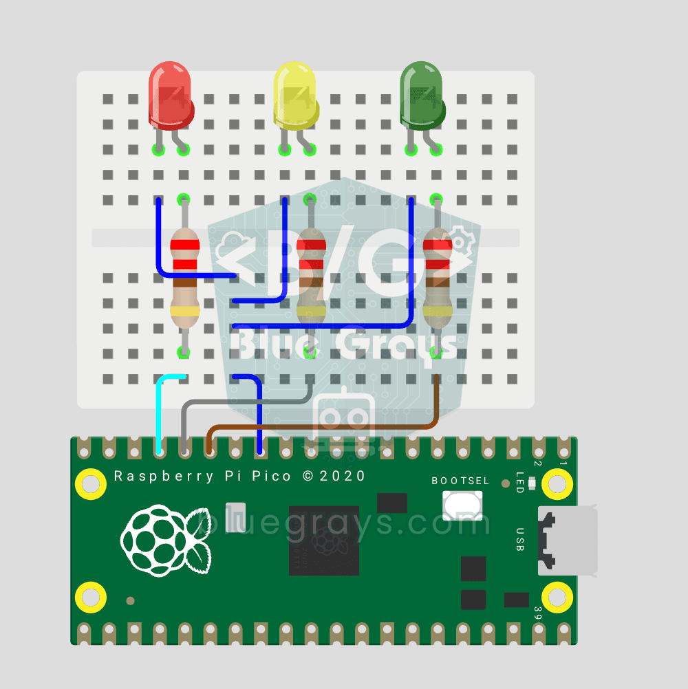
We recreate real traffic light logic with red, yellow and green LEDs, the first Pico project to move up to 3 LEDs! Green says "go" for 4 seconds, yellow "get ready" for 1.5 seconds, red "stop" for 3 seconds, and red+yellow "set off" for 1 second (the European traffic light pattern). You'll learn to define functions (def all_off()), state machine logic and multi-GPIO synchronization.